
Arista_EOS_RoCEv2_Lossless_Config
On Cisco NX-OS, enabling PFC for RoCE normally involves several MQC (Modular QoS CLI class-map -> policy-map -> system qos) layers. On Arista EOS, basic PFC can be enabled directly on an interface with two commands:
priority-flow-control on
priority-flow-control priority 3 no-drop
Note: these commands cannot be executed in an EVE-NG lab. PFC is a hardware feature — the pause frames are generated and honored by the switching ASIC — and the virtual vEOS-lab image has no such hardware, so EOS rejects the configuration outright. Real output from a vEOS-lab node:
Leaf1(config-if-Et1)#priority-flow-control on
% The hardware does not support priority flow control, or forwarding agent is still initializing.
Leaf1(config-if-Et1)#priority-flow-control priority 3 no-drop
% The hardware does not support priority flow control, or forwarding agent is still initializing
Everything in this guide therefore needs physical Arista switches to practice on; the same class of limitation applies to ECN marking, buffer thresholds, and the PFC watchdog. This mirrors the vEOS-lab VXLAN multicast limitation documented in the Arista VXLAN EVPN lab post: control-plane features virtualize, data-plane features often do not.
Those two commands are only the PFC portion of a complete RoCEv2 design. A deployable configuration must also define classification, queue scheduling, ECN, watchdog behavior, buffer thresholds, and the policy on every possible congestion point.
This guide uses EOS 4.36 and a concrete example rather than claiming one configuration fits every Arista platform. The example assumes:
- Routed point-to-point switch links that trust DSCP.
- RoCE data is marked DSCP 26 and mapped to TC/queue 3.
- NVIDIA CNP packets are marked DSCP 48 and mapped to TC/queue 6.
- The leaf exposes
uc-tx-queue; the example spine exposestx-queue. - CLI availability and threshold units are verified on the exact switch model and EOS release before deployment.
Demo topology
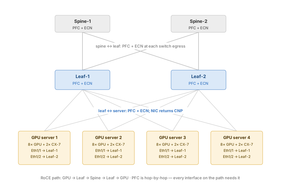
PFC is a hop-by-hop mechanism, so it must be enabled consistently on every lossless hop: server-facing leaf ports, leaf uplinks, and spine-facing ports. ECN is an egress congestion signal and must be configured at every egress where the RoCE queue can become congested, including the spines. The leaf and spine can use different thresholds because their ASICs and link speeds may differ.
The lossless cheat sheet
| Term | What it is | Role |
|---|---|---|
| ECN | Explicit Congestion Notification | A congested switch marks an ECN-capable packet instead of immediately dropping it |
| CNP | Congestion Notification Packet | The receiver tells the sender that it observed ECN congestion marks |
| PFC | Priority Flow Control | A switch pauses one Ethernet priority on its peer when lossless headroom is threatened |
| DCQCN | Data Center Quantized Congestion Notification | The sender NIC reduces its rate in response to CNPs |
| SP -> TC -> Q | Switch Priority -> Traffic Class -> Queue | The classification and queueing path used by the switch |
| PFC pause storm | Continuous or excessive PFC pause reception | Can leave an egress queue stuck; the PFC watchdog is designed to detect this condition |
| PFC deadlock | A cyclic dependency between paused queues or links | A fabric-wide design failure; it is not simply another name for a pause storm |
Four points to keep straight:
- The normal control sequence is ECN marking -> CNP return -> DCQCN slows the sender -> PFC only as a last resort.
- The switch performs ECN marking and PFC; DCQCN runs on the server NIC.
- A watchdog mitigates stuck queues caused by persistent pause reception, but it does not prove that the topology is free from every possible cyclic PFC deadlock.
- The ingress trust mode decides whether packet DSCP or 802.1p CoS is used to derive the traffic class.
One no-drop data queue, with CNP kept separate
The reference policy uses one PFC-enabled no-drop queue for RoCE data. CNP uses a separate strict-priority queue but remains lossy:
| Traffic | Example marking | TC / queue | Scheduling | ECN | PFC |
|---|---|---|---|---|---|
| RoCE data | DSCP 26 (AF31) | 3 | WRR, approximately 95% | Yes | Yes |
| CNP | DSCP 48 (CS6) | 6 | Strict priority | No | No |
| Network control | DSCP 56 (CS7) | 7 | Platform-reserved control queue | No | No |
| Best effort | DSCP 0-7 | 1 | WRR, approximately 5% | No | No |
CNP must not sit behind congested RoCE data, but that does not require making CNP another PFC-enabled queue. Arista’s published AI-fabric example likewise protects only the RoCE data queue with PFC and ECN. That guide’s CNP marking differs from this NVIDIA-oriented DSCP 48 example, which is why host marking and switch mapping must be checked together.
1. Classification and platform-specific queue mapping
Map the host markings to the intended traffic classes:
switch(config)# qos map dscp 26 to traffic-class 3
switch(config)# qos map dscp 48 to traffic-class 6
Both commands restate the documented default DSCP-to-traffic-class map rather than override it. EOS publishes the same default across its platform families, Arad, Jericho, Trident, Trident II and Tomahawk among them, and it already sends DSCP 24-31 to traffic class 3 and DSCP 48-55 to traffic class 6:
| DSCP | 0-7 | 8-15 | 16-23 | 24-31 | 32-39 | 40-47 | 48-55 | 56-63 |
|---|---|---|---|---|---|---|---|---|
| Traffic class | 1 | 0 | 2 | 3 | 4 | 5 | 6 | 7 |
Note the inversion at the low end: DSCP 0-7 map to traffic class 1 and DSCP 8-15 to traffic class 0, not the other way round. That is a systematic EOS convention rather than a typo, and it appears the same way in the default CoS-to-traffic-class map. It is also what places default-marked traffic at DSCP 0 into queue 1, which is why the best-effort row in the policy above targets queue 1 rather than queue 0.
Configuring the two maps explicitly is still worth doing. It records the intent for anyone reading the running configuration, and it keeps the policy correct on a platform or release whose defaults differ from the table above.
DSCP 26 here versus DSCP 24 elsewhere on this blog. This post follows NVIDIA’s Arista-facing examples, which mark RoCE data DSCP 26 (AF31); the RoCEv2 end-to-end guide and the Cumulus material standardize on DSCP 24 (CS3). In a mixed Arista + Cumulus fabric the difference is more forgiving than it looks: both platforms’ default maps classify the whole DSCP 24–31 block into traffic class / switch priority 3 (the table above; Cumulus’s RoCE profile does the same), so 24 and 26 land in the same lossless queue either way. The forgiveness ends where exact-match classification begins — an NX-OS class-map matching
dscp 24will silently miss DSCP 26, the ConnectX host stamps exactly one value that every capture filter (ip.dsfield.dscp == 24) and counter then keys on, and any custom mapping that lists specific values instead of the block reintroduces the mismatch. So if this fabric runs alongside the configurations from the other guides, pick one value and change every hop consistently — using 24 here is simplyqos map dscp 24 to traffic-class 3, still inside the default block.
Then map those traffic classes to transmit queues. The map target is tx-queue on every platform:
switch(config)# qos map traffic-class 3 to tx-queue 3
switch(config)# qos map traffic-class 6 to tx-queue 6
That is worth stating precisely, because uc-tx-queue appears in the leaf profile below and the two are easy to conflate. uc-tx-queue is a configuration sub-mode on platforms that expose separate unicast queues, and section 2 uses it correctly in that role. It is not a qos map target. EOS documents only qos map traffic-class ... to tx-queue, and on Arad/Jericho the manual states the switch defines a single traffic-class-to-transmit-queue map covering both unicast and multicast.
Queue 7 needs no mapping and cannot be remapped: traffic class 7 and transmit queue 7 are permanently associated in EOS and reserved for control traffic. Confirm the resulting maps with show qos maps before applying a service profile.
2. Leaf QoS profile
This sample leaf profile uses the unicast queue hierarchy commonly exposed on Broadcom-based leaf platforms:
Leaf-1(config)# qos profile ROCE-LEAF
Leaf-1(config-qos-profile-ROCE-LEAF)# priority-flow-control on
Leaf-1(config-qos-profile-ROCE-LEAF)# priority-flow-control priority 3 no-drop
Leaf-1(config-qos-profile-ROCE-LEAF)# uc-tx-queue 1
Leaf-1(config-qos-profile-ROCE-LEAF-uc-txq-1)# no priority
Leaf-1(config-qos-profile-ROCE-LEAF-uc-txq-1)# bandwidth percent 5
Leaf-1(config-qos-profile-ROCE-LEAF-uc-txq-1)# uc-tx-queue 3
Leaf-1(config-qos-profile-ROCE-LEAF-uc-txq-3)# no priority
Leaf-1(config-qos-profile-ROCE-LEAF-uc-txq-3)# bandwidth percent 95
Leaf-1(config-qos-profile-ROCE-LEAF-uc-txq-3)# random-detect ecn minimum-threshold 256 kbytes maximum-threshold 512 kbytes max-mark-probability 100 weight 0
Leaf-1(config-qos-profile-ROCE-LEAF-uc-txq-3)# uc-tx-queue 6
Leaf-1(config-qos-profile-ROCE-LEAF-uc-txq-6)# priority strict
Command by command:
priority-flow-control on+priority 3 no-drop— enables PFC processing on ports carrying this profile and declares priority 3 (the RoCE data class) lossless. Only priority 3: every other priority stays ordinary drop-eligible traffic.uc-tx-queue <n>— enters the scheduler configuration for one unicast transmit queue (the Broadcom-style hierarchy; the spine’s Jericho-style equivalent istx-queue).no priority— takes the queue out of strict-priority mode and makes it a weighted round-robin (WRR) participant. Only WRR queues use thebandwidth percentweights.bandwidth percent 95/bandwidth percent 5— a scheduling weight, and the phrasing matters: it is not 95% of the interface rate, and it is not a cap. Strict-priority queues (queue 6 here, plus the platform control queue) are always served first; whatever bandwidth remains is then divided among the backlogged WRR queues in proportion to their weights — 95:5 between queue 3 and queue 1 when both have traffic. The scheduler is work-conserving, so when queue 1 is idle and nothing strict is transmitting, queue 3 can use effectively the entire interface. The semantics are the same as NX-OSbandwidth remaining percent, dissected with worked numbers in the QoS concepts post.random-detect ecn minimum-threshold 256 kbytes maximum-threshold 512 kbytes ...— the two values are queue-occupancy action points, not a buffer allocation. The port still draws packet memory from the ASIC’s shared buffer pool; these thresholds only define when marking happens as queue 3’s depth grows. Buffer allocation, PFC XOFF, and tail-drop limits are all separate mechanisms — and the design intent is that these ECN thresholds sit below the PFC trigger point, so senders get slowed before pause frames become necessary (section 6 tunes exactly this relationship).max-mark-probability 100— the ceiling of the marking-probability ramp: the percentage of eligible packets that get marked once queue depth reaches the maximum threshold.100means marking becomes deterministic at 512 KB — every eligible packet is marked. This is a real design choice, not boilerplate: the Cisco reference design in the end-to-end guide usesdrop-probability 7, a gentle 7% ceiling suited to its wide 150 KB–3000 KB band, while this Arista profile pairs a narrow band (256–512 KB) with a 100% ceiling — softer start, harder finish.weight 0— the exponential-weighting constant for the queue-depth measurement.0means the marking decision uses the instantaneous queue depth; larger values average the depth over time, which smooths out bursts but reacts late. Instantaneous is the standard choice for RoCE: a microburst must be marked while it is happening, not after a moving average catches up.uc-tx-queue 6+priority strict— the CNP queue: strict priority means it is served ahead of all WRR queues whenever it holds a packet, so congestion feedback is never stuck behind the very data that caused the congestion.
So when exactly does the CE mark (ECN bits 11) get written? Not only beyond 512 KB — that’s the common misreading. The marking probability ramps linearly between the two thresholds:
CE-mark probability for arriving ECT packets

100% ┤                          ┌─────────────────
     │                        / ← max-mark-probability 100
     │                      /
     │                    /
     │                  /
  0% ┼────────────────/
     └───────────── 256 KB ── 512 KB ──────────→  queue-3 depth
       no marking      probabilistic      every ECT
                       marking ramp       packet marked
- Below 256 KB: no action — RoCE packets pass with their ECT(0) marking (
10) untouched. - Between 256 KB and 512 KB: each arriving packet is marked with a probability that climbs from ~0% toward 100% as the queue deepens. The first CE marks therefore appear shortly after the queue crosses 256 KB — sparsely at first, which is the point: a few early CNPs slow senders gently before the queue gets serious.
- At and beyond 512 KB: every arriving packet is marked CE — a continuous stream of CNPs back to the senders.
- Two boundary conditions: only ECT-capable packets (
01/10) can be marked — a packet sent as Not-ECT (00) can never become11and gets dropped instead once drop limits engage; and marking never replaces dropping entirely — if senders ignore the CNPs and the shared buffer truly fills, tail drop remains the final backstop. The codepoints themselves are dissected in the concepts post’s ECN section.
The ECN values are starting values from an Arista reference design, not universal constants. Validate them against the port speed, cable delay, oversubscription, ASIC cell size, shared-buffer policy, and NIC reaction time.
Apply the profile on an explicitly routed, DSCP-trusted interface:
Leaf-1(config)# interface Ethernet1
Leaf-1(config-if-Et1)# no switchport
Leaf-1(config-if-Et1)# mtu 9214
Leaf-1(config-if-Et1)# qos trust dscp
Leaf-1(config-if-Et1)# service-profile ROCE-LEAF
no switchport makes the port routed, for which DSCP trust is normally the default. The explicit qos trust dscp documents the intent and keeps the configuration correct if it is copied to a switched port, whose default trust mode is CoS.
Enable ECN counters under the interface queue, not inside the QoS profile:
Leaf-1(config)# interface Ethernet1
Leaf-1(config-if-Et1)# uc-tx-queue 3
Leaf-1(config-if-Et1-uc-txq-3)# random-detect ecn count
Despite the near-identical name, this is a different job from the profile’s random-detect ecn minimum-threshold .... The profile command does the marking — it is the policy that rewrites ECT to CE when the queue crosses its thresholds. random-detect ecn count only counts it: it tells the ASIC to allocate a hardware counter that increments every time this queue on this interface CE-marks a packet. Without it, the switch happily marks packets but records nothing — show qos interfaces ethernet 1 counters shows no ECN column, and you have no switch-side evidence that ECN is firing. That makes an unverifiable ECN policy a diagnostic dead end: the “switch ECN counters rise but no CE packets reach the endpoint” comparison (use case 2 in the RDMA tuning post’s capture guide) needs this counter to exist. Counting is opt-in because ASIC counter resources are finite and shared: EOS does not burn one per queue per port by default, so you enable it exactly where you intend to watch.
Some platforms also require hardware counter feature ecn out — a global knob that reserves counter resources for egress ECN counting — before the per-queue command takes effect. Check platform support and verify that the counter command was accepted before relying on ECN statistics.
Verify the leaf configuration
Validate the profile, its interface attachment, classification, ECN, and PFC before moving on to the spine:
Leaf-1# show qos profile ROCE-LEAF
Leaf-1# show qos profile summary
Leaf-1# show qos interfaces ethernet 1
Leaf-1# show qos interfaces ethernet 1 trust
Leaf-1# show priority-flow-control
Leaf-1# show priority-flow-control counters
Preserve the ECN check as a standalone command because its output confirms both the queue selection and the programmed thresholds:
Leaf-1# show qos interfaces ethernet 1 ecn
Tx-Queue  Threshold  ECN Min     ECN Max
          Unit       Threshold   Threshold
--------  ---------  ---------   ---------
3         kbytes     256         512
Confirm the following in the output:
ROCE-LEAFis attached toEthernet1.- The operational trust mode is DSCP.
- Queue 3 has ECN enabled with the intended minimum and maximum thresholds.
- PFC is enabled and active only for priority 3.
- PFC counters are zero or low before load testing; during a test, evaluate their rate of increase rather than treating every non-zero value as a failure.
3. Spine QoS profile
The spine is another possible congestion point, so it needs ECN as well as PFC. A Jericho-style spine may expose tx-queue rather than uc-tx-queue and can require different thresholds:
Spine-1(config)# qos profile ROCE-SPINE
Spine-1(config-qos-profile-ROCE-SPINE)# priority-flow-control on
Spine-1(config-qos-profile-ROCE-SPINE)# priority-flow-control priority 3 no-drop
Spine-1(config-qos-profile-ROCE-SPINE)# tx-queue 1
Spine-1(config-qos-profile-ROCE-SPINE-txq-1)# no priority
Spine-1(config-qos-profile-ROCE-SPINE-txq-1)# bandwidth percent 5
Spine-1(config-qos-profile-ROCE-SPINE-txq-1)# tx-queue 3
Spine-1(config-qos-profile-ROCE-SPINE-txq-3)# no priority
Spine-1(config-qos-profile-ROCE-SPINE-txq-3)# bandwidth percent 95
Spine-1(config-qos-profile-ROCE-SPINE-txq-3)# random-detect ecn minimum-threshold 512 kbytes maximum-threshold 768 kbytes max-mark-probability 100
Spine-1(config-qos-profile-ROCE-SPINE-txq-3)# tx-queue 6
Spine-1(config-qos-profile-ROCE-SPINE-txq-6)# priority strict
The commands mirror the leaf profile in section 2 — same PFC scope, same WRR-weight semantics for bandwidth percent 95 (a share of what remains after the strict queues, not a cap), same strict CNP queue. Three differences are deliberate:
tx-queueinstead ofuc-tx-queue— the Jericho-style queue hierarchy exposes a single queue set rather than separate unicast queues; it is the same scheduler role under a different name.- Higher ECN thresholds (512/768 KB versus the leaf’s 256/512 KB) — still queue-occupancy action points, not buffer carving. A spine port aggregates many leaf-to-leaf flows and rides longer paths, so its queue legitimately runs deeper before marking should start; thresholds that fire too early on an aggregation port mark healthy multiplexing as congestion.
- No explicit
weight 0— this platform’s syntax takes the instantaneous-depth default rather than requiring it spelled out; verify with theshow qos interfaces ... ecnoutput below rather than assuming.
Apply it to every leaf-facing spine interface and enable the corresponding per-interface ECN counter:
Spine-1(config)# interface Ethernet1
Spine-1(config-if-Et1)# no switchport
Spine-1(config-if-Et1)# mtu 9214
Spine-1(config-if-Et1)# qos trust dscp
Spine-1(config-if-Et1)# service-profile ROCE-SPINE
Spine-1(config-if-Et1)# tx-queue 3
Spine-1(config-if-Et1-txq-3)# random-detect ecn count
If the leaf and spine use the same ASIC family, their queue hierarchy may be the same. They should still be kept as separate named profiles when thresholds or scheduler behavior differ.
Verify the spine the same way as the leaf, and confirm that the spine’s own thresholds took effect rather than the leaf’s:
Spine-1# show qos interfaces ethernet 1 ecn
Tx-Queue  Threshold  ECN Min     ECN Max
          Unit       Threshold   Threshold
--------  ---------  ---------   ---------
3         kbytes     512         768
The 512/768 values are what distinguish this output from the leaf’s in section 2. A spine still reporting 256/512 means the leaf profile was applied by mistake.
4. Verify PFC, QoS, and trust mode
Sections 2 and 3 checked each device as it was configured. This is the checkpoint once both are in place: confirm the assembled policy before moving on to DCBX and threshold tuning. The section 9 checklist repeats these commands for diagnosing a fabric that is already broken.
Leaf-1# show priority-flow-control
Port       Enabled  Priorities  Active  Note
---------  -------  ----------  ------  -------------
Ethernet1  Yes      3           Yes     DCBX disabled
Only priority 3 is expected because CNP and control traffic are not no-drop priorities in this policy.
Check the other pieces independently:
Leaf-1# show qos profile ROCE-LEAF
Leaf-1# show qos maps
Leaf-1# show qos interfaces ethernet 1 trust
Leaf-1# show qos interfaces ethernet 1 ecn
Leaf-1# show qos interfaces ethernet 1 ecn counters queue
Leaf-1# show priority-flow-control counters
PFC counters are operational signals, not pass/fail values. A small number of pause frames can occur during bursts. Continuously high or increasing rates indicate sustained congestion, insufficient headroom, overly high ECN thresholds, or a peer that is not reacting to CNPs.
5. DCBX: optional for a statically enforced policy
DCBX is disabled by default on EOS. Enable IEEE DCBX only when the design requires exchanging PFC and application-priority information with the peer:
Leaf-1(config)# interface Ethernet1
Leaf-1(config-if-Et1)# dcbx mode ieee
Verify it with an interface-specific command:
Leaf-1# show dcbx ethernet 1
Ethernet1:
 IEEE DCBX is enabled and active
 ...received PFC and application-priority TLV details...
Do not look for a mandatory literal negotiated state. Inspect whether IEEE DCBX is enabled and active, whether LLDP is operating, and whether the expected TLVs were received. Statically configured priority-flow-control on and priority-flow-control priority 3 no-drop can operate with DCBX disabled; DCBX is not a prerequisite for that static policy.
6. ECN threshold tuning
ECN is configured per egress queue. The marking probability rises between the minimum and maximum thresholds; at or above the maximum, ECN-capable traffic is marked at the configured maximum probability.
Thresholds must be tuned from measurement rather than a fixed percentage of a supposed “port buffer.” Many Arista platforms use shared buffers, different cell sizes, and different admission-control behavior. Start with the platform reference values, then observe:
- ECN-marked packets and marking rate.
- PFC transmit and receive rates, not just cumulative values.
- Queue occupancy and buffer watermarks during representative incast.
- Packet drops, CNP rate, and sender throughput convergence.
As a general starting heuristic, when the platform exposes a known effective buffer budget for the RoCE queue:
minimum-threshold: start at 40-50% of the verified effective queue-buffer budget.maximum-threshold: start at 75-85% of that same budget.- Watch the PFC counter rate: if TxPFC keeps climbing after ECN is active, reduce the minimum threshold by approximately 20% and retest.
Treat these percentages as a tuning aid, not a platform default. The denominator is the buffer budget effectively available to the queue under the active ASIC and MMU (memory management unit) profile, not the switch’s total packet memory or an assumed fixed per-port buffer.
Lower the ECN threshold if PFC fires before senders react. Increase it cautiously if ECN marking is excessive during harmless microbursts. Always keep enough headroom for in-flight traffic after a pause is generated.
7. FADT release boundaries
FADT — Fair Adaptive Dynamic Threshold — is Arista’s answer to a problem every shared-buffer switch has: where do you set a queue’s action thresholds (PFC XOFF, drop points) when the buffer is one shared pool rather than fixed per-port slices?
A static threshold — a fixed byte value like the ECN thresholds in sections 2 and 3 — has to be provisioned for the worst case. Set it high and a handful of congested ports can drain the shared pool, leaving nothing for the rest; set it low and a single burst gets paused or dropped while most of the buffer sits idle. Static values are predictable but always wrong in one direction.
A dynamic threshold instead computes each queue’s limit continuously from what is left in the shared pool, conceptually:
threshold ≈ alpha × free shared buffer
When the switch is quiet, the free pool is large, so a single bursting queue gets a generous threshold and absorbs the burst without pausing. As more queues congest, the free pool shrinks, and every queue’s threshold shrinks with it — the pool divides itself among the active consumers instead of first-come-first-served exhaustion. That self-scaling division is the “fair” and “adaptive” in the name.
Applied to PFC — the case this post cares about — FADT means the XOFF point is not a fixed byte count but moves with buffer pressure: pause fires later (more burst absorption) when buffer is plentiful, and earlier (protecting the lossless guarantee for everyone) when many lossless queues are competing. The PFC-specific FADT feature assigns these dynamic-threshold profiles to interface/priority groups. Note the contrast with everything configured earlier in this post: the ECN thresholds in sections 2, 3, and 6 are static byte values you chose; the PFC trigger on a FADT-enabled platform is a computed, moving target — which is one more reason section 6’s advice measures ECN’s health against observed PFC counter behavior rather than against an assumed fixed XOFF number.
FADT is not one feature with one universal introduction release:
- General Fair Adaptive Dynamic Threshold support for shared VoQ (virtual output queue) resources is documented from EOS 4.22.0F.
- PFC-specific FADT configuration, which assigns PFC profiles to interface/priority groups, is documented from EOS 4.35.0F on supported platforms.
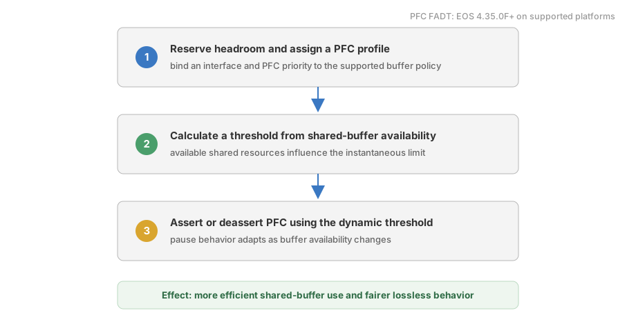
Do not assume that PFC FADT is enabled merely because the switch runs an AI-oriented configuration template. Availability, defaults, profile syntax, and supported buffer controls vary by ASIC and EOS release. Check the platform-specific EOS guide and inspect the active PFC/buffer profile before relying on it.
EOS 4.34.2F is associated with some PFC visibility improvements, such as buffer counters on supported platforms, but it should not be presented as the universal FADT introduction release.
8. PFC watchdog
The watchdog monitors PFC-enabled egress queues that also have guaranteed bandwidth. All three timers are in seconds: timeout and recovery-time accept 0.01 to 60, and polling-interval accepts 0.005 to 30. The values below satisfy EOS’s timing relationship because the polling interval is no greater than half the smaller of timeout and recovery time:
Leaf-1(config)# priority-flow-control pause watchdog default timeout 0.20
Leaf-1(config)# priority-flow-control pause watchdog default recovery-time 0.20
Leaf-1(config)# priority-flow-control pause watchdog default polling-interval 0.10
Leaf-1(config)# priority-flow-control pause watchdog action drop
With automatic recovery and all three values configured:
polling-interval <= min(timeout, recovery-time) / 2
For the example above, 0.10 <= min(0.20, 0.20) / 2, so the configured polling interval is valid. If this relationship is violated, EOS can substitute an automatically calculated interval and issue CLI/syslog warnings.
The watchdog only monitors queues that have guaranteed bandwidth configured, so the RoCE queue needs it:
Leaf-1(config)# interface Ethernet1
Leaf-1(config-if-Et1)# tx-queue 3
Leaf-1(config-if-Et1-txq-3)# bandwidth guaranteed 100
That 100 is 100 kbps, not 100 percent. EOS uses an explicit percent keyword when it means a share, as in the profile’s bandwidth percent 95; a bare number here is a rate, in the same kbps unit as the sibling shape rate command.
A value that small is deliberate. Arista’s stated reason for requiring it is that guaranteed bandwidth “is needed to ensure starvation due to higher priority traffic is not wrongly flagged as a stuck-queue due to congestion.” In this design queue 6 is strict priority, so it can legitimately starve queue 3 - and a starved queue looks exactly like a PFC-stuck queue to a watchdog. A small guarantee ensures queue 3 always receives some service, so a queue that still will not drain is genuinely stuck. It is a disambiguation floor, not a capacity allocation, and it sits far below what the 95% WRR weight already grants the queue.
Two caveats before copying this. The EOS QoS manual describes guaranteed bandwidth as supported only on Trident II platforms; because the watchdog depends on it, confirm that this entire section applies to the hardware in use. And Arista documents the command under tx-queue, which is why the block above uses tx-queue rather than the uc-tx-queue hierarchy the leaf profile uses in section 2 - on a platform that exposes both, verify which sub-mode accepts bandwidth guaranteed.
action drop drops traffic associated with the stuck queue while the condition is handled. Use action errdisable only when disabling the entire port is the intended failure policy. Verify both status and counters:
Leaf-1# show priority-flow-control status
Leaf-1# show priority-flow-control counters watchdog
9. Troubleshooting checklist
| Purpose | Command |
|---|---|
| Applied QoS profile | show qos profile ROCE-LEAF and show qos profile summary |
| Ingress trust mode | show qos interfaces ethernet 1 trust |
| DSCP/TC/queue mappings | show qos maps |
| PFC state and watchdog status | show priority-flow-control status |
| PFC frame counters | show priority-flow-control counters |
| Watchdog events | show priority-flow-control counters watchdog |
| ECN thresholds | show qos interfaces ethernet 1 ecn |
| ECN marking counters | show qos interfaces ethernet 1 ecn counters queue |
| Queue and interface drops | show interfaces ethernet 1 counters queue detail |
| Buffer watermarks | Platform-specific PFC buffer and show buffer commands |
| DCBX and received TLVs | show dcbx ethernet 1 |
During a traffic test, verify classification first, then ECN, then PFC, then the watchdog. A packet mapped to the wrong queue cannot be fixed by changing ECN thresholds.
10. Arista vs Cisco at a glance
| Dimension | Arista EOS | Cisco NX-OS |
|---|---|---|
| Basic PFC enablement | Two direct commands or reusable QoS profile | Commonly implemented through MQC and system QoS |
| DCBX | Disabled by default; optional for static PFC | Behavior depends on platform and configured policy |
| ECN location | Per egress tx-queue or uc-tx-queue | Typically under a queuing policy |
| Adaptive thresholds | General FADT from 4.22; PFC FADT from 4.35 on supported platforms | Platform-specific dynamic buffer mechanisms |
| Important qualification | Queue CLI and thresholds vary by ASIC | Policy syntax and supported combinations vary by ASIC |
Summary
A safe RoCEv2 configuration is more than two PFC commands. The complete design must keep classification, ECN, PFC, CNP scheduling, watchdog timing, and host markings consistent end to end.
For this example, remember the operational contract:
- DSCP 26 -> TC/queue 3 -> ECN and PFC.
- DSCP 48 -> TC/queue 6 -> strict scheduling without PFC.
- ECN is present at both leaf and spine congestion points.
- Leaf and spine profiles are separated because ASIC queue hierarchies and thresholds can differ.
- ECN counters are enabled per interface queue.
- DCBX is verified through active state and received TLVs, not a fictional mandatory
negotiatedfield. - Watchdog polling satisfies the EOS timeout relationship.
For the NVIDIA/Cumulus host-side marking configuration, see RoCE on Cumulus Linux. For generating RDMA test traffic, see perftest.