
PIM Sparse Mode in Detail
A step-by-step walk through the PIM Sparse Mode (PIM-SM) control plane — from a receiver’s IGMP report through shared-tree construction, source registration, the native source tree, and the optional shortest-path-tree switchover — then how to make the Rendezvous Point redundant with Anycast RP. Section 21 covers how multicast trees spread across equal-cost paths; for the Designated Router versus Assert election — and how multicast ECMP interacts with those elections when two PIM routers share a receiver VLAN — see the companion post PIM DR, Assert, and Multicast ECMP.
1. Overview
Protocol Independent Multicast Sparse Mode (PIM-SM) builds multicast distribution trees only where receivers explicitly request traffic. It is intended for networks where multicast receivers are sparsely distributed.
PIM-SM uses the existing unicast routing table for path selection. PIM does not calculate routes to the source or Rendezvous Point (RP); it uses unicast routes to perform Reverse Path Forwarding (RPF) decisions.
This document uses:
S— multicast sourceG— multicast group(*,G)— any-source state for groupG(S,G)— source-specific state for sourceSand groupG- LHR — last-hop router near the receiver
- FHR — first-hop router near the source
- RP — Rendezvous Point
- RPT — RP tree or shared tree
- SPT — shortest-path tree
2. Complete Process
The whole control-plane and data-plane progression at a glance — the twelve numbered steps are detailed in the sections that follow:
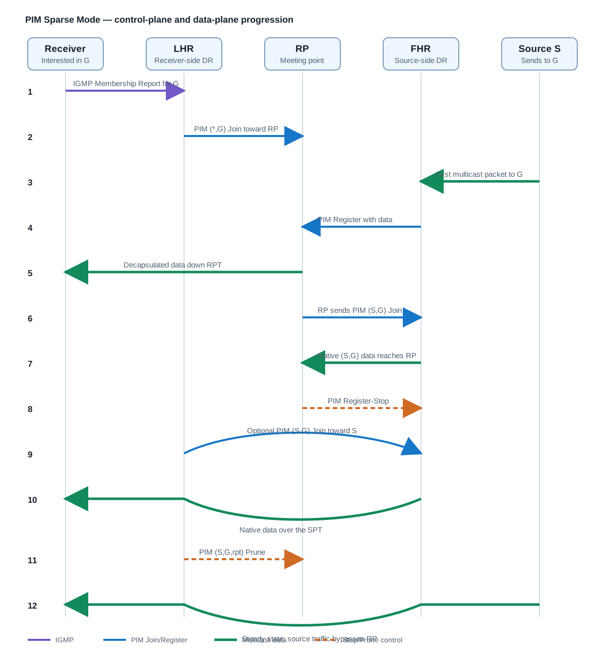
The same progression, clickable — step through the twelve steps one at a time (or jump to a phase) and watch each message drawn against the trees the earlier steps already built:
3. Receiver Announces Membership
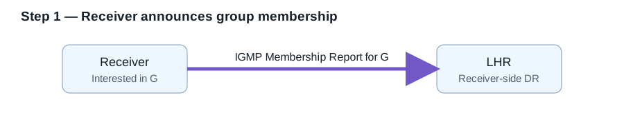
The receiving host sends an IGMP Membership Report for group G.
IGMP operates only between hosts and their local multicast router. It is not used to build multicast trees between routers.
The Designated Router on the receiver subnet becomes the LHR and records that its receiver-facing interface needs group G:
Group: G
Outgoing-interface list:
  Receiver LAN
If multiple receivers on the same LAN join the same group, the router normally maintains one outgoing interface for that LAN rather than one routed entry per receiver.
4. LHR Joins the Shared Tree
The LHR determines the RP associated with group G. RP information may come from:
- Static RP configuration
- PIM Bootstrap Router mechanisms
- Auto-RP on platforms that support it
- Anycast RP designs
The LHR looks up the unicast route to the RP:
RPF interface for (*,G) = interface toward the RP
RPF neighbor for (*,G)  = next-hop router toward the RP
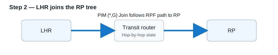
It then sends a PIM (*,G) Join to that RPF neighbor.
The PIM Join is hop-by-hop. It is not normally a packet sent directly from the LHR to the RP. Each intermediate router:
- Receives the Join.
- Creates or refreshes
(*,G)state. - Adds the downstream interface to its outgoing-interface list.
- Sends another
(*,G)Join to its own RPF neighbor toward the RP.
The resulting shared tree is:
RP
└── Transit router
    └── LHR
        └── Receiver LAN
This tree is receiver-driven: PIM-SM does not build a branch until a receiver requests the group.
5. Source Begins Transmitting
The source sends packets addressed to group G. A multicast sender does not need to join its own group.
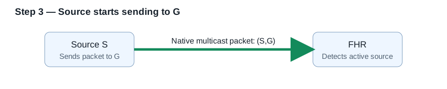
The PIM Designated Router on the source subnet becomes the FHR. It detects the directly connected active source and creates (S,G) state:
(S,G)
Incoming interface:
  Source LAN
For a directly connected source, the source-facing interface is the correct RPF interface.
6. FHR Registers the Source with the RP
Initially, no native multicast tree may exist between the FHR and RP. The FHR therefore encapsulates the complete multicast packet inside a unicast PIM Register:
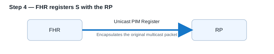
Outer IP packet:
  Source:      FHR
  Destination: RP
  Protocol:    PIM

PIM Register payload:
  Original multicast packet
    Source:      S
    Destination: G
Because the Register is unicast, intermediate routers do not require multicast state to carry it to the RP.
When the RP receives the Register, it:
- Decapsulates the multicast packet.
- Learns that source
Sis active for groupG. - Checks whether it has downstream
(*,G)receiver state. - Forwards the packet down the shared tree when receivers exist.
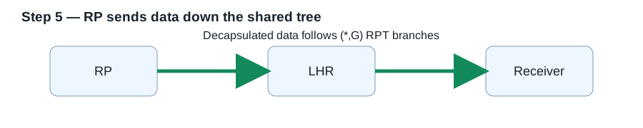
The initial data path is therefore:
Source → FHR == PIM Register ==> RP → RPT → LHR → Receiver
7. RP Builds a Native Source Tree
Register encapsulation is useful for source discovery but inefficient for sustained traffic.
The RP sends an (S,G) Join toward S. This Join follows the RP’s unicast RPF path to the source:
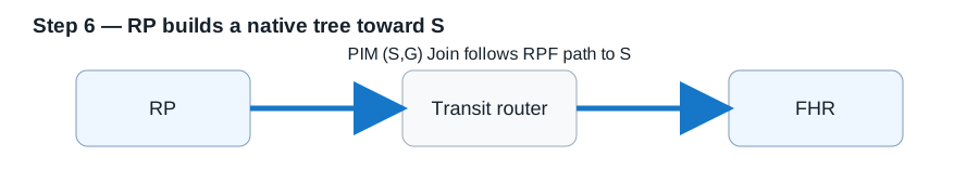
RP → RPF neighbor toward S → ... → FHR
Every router along the path creates or refreshes (S,G) state:
(S,G)
Incoming interface:
  Toward S

Outgoing-interface list:
  Toward RP
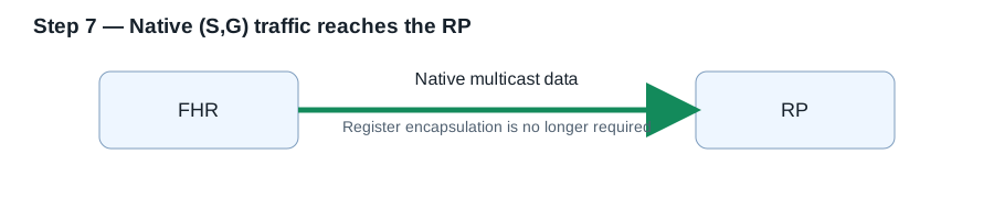
Native multicast packets can now travel from the FHR to the RP without Register encapsulation.
8. Register-Stop
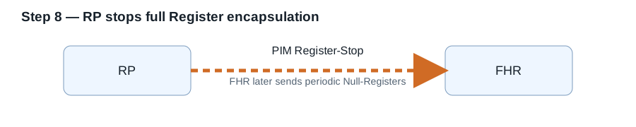
After the RP receives native (S,G) traffic, it sends a PIM Register-Stop to the FHR.
Two different triggers for Register-Stop
This is the point most walkthroughs skip: the RP sends Register-Stop in two distinct situations, for opposite reasons. RFC 7761 states the rule as a single condition — the RP sends Register-Stop(S,G) when it is receiving the traffic natively (SPTbit set) or it has no outgoing interfaces for the group (no receivers) — but those two clauses describe two very different stories:
| Trigger | Are there receivers? | What it means | Does the RP build the source tree? |
|---|---|---|---|
Native (S,G) traffic arrives (SPTbit set) | Yes | “Stop encapsulating — I now receive it natively.” | Yes — the SPT built in steps 6–7 |
| Outgoing-interface list is empty | No | “I do not want this traffic at all.” | No — no join is sent toward the source |
With receivers — the case steps 6–8 walk. The RP first joins the SPT toward the source and pulls native traffic, then sends Register-Stop as an optimization. Data keeps flowing to the receivers the whole time. RFC 7761, Section 3.2 describes this exactly:
While the RP is in the process of joining the source-specific tree for S, the data packets will continue being encapsulated to the RP. When packets from S also start to arrive natively at the RP, the RP will be receiving two copies of each of these packets. At this point, the RP starts to discard the encapsulated copy of these packets, and it sends a Register-Stop message back to S’s DR to prevent the DR from unnecessarily encapsulating the packets.
In the pseudocode of Section 4.4.2, “packets start to arrive natively” is precisely the moment
SPTbit(S,G)is set to TRUE — which is why that single flag is the whole trigger for this case.Without receivers — the RP has nowhere to forward the decapsulated data, so it sends Register-Stop almost immediately, before building anything. No source tree is created and nothing is forwarded; the goal is simply to stop the FHR from wasting bandwidth registering a stream no one wants. This is the
inherited_olist(S,G) == NULLclause of the same §4.4.2 condition.
The important takeaway: Register-Stop is not proof that receivers exist. A source with zero listeners still triggers Register-Stop — it just means the RP declined the traffic rather than switched to native forwarding.
The FHR then stops sending full-data Registers:
Before:
FHR == encapsulated multicast data ==> RP

After:
FHR ===== native multicast data =====> RP
FHR ----- periodic Null-Register ----> RP
Steady state: the Null-Register / Register-Stop heartbeat
Once suppressed, the FHR does not keep pushing data — but it does not go silent either. Its per-(S,G) register state machine (RFC 7761, Section 4.4.1) enters a suppressed (Prune) state and starts a Register-Stop Timer (Register_Suppression_Time, default 60 s). While that timer runs it sends no data-encapsulated Registers at all. But Register_Probe_Time (default 5 s) before the timer expires, it sends a single Null-Register — a Register with the Null bit set, header only, no payload — as a probe: “source S is still active; do you still not need me to register?”
Each Null-Register re-runs the RP’s Section 4.4.2 logic. Because the RP is still receiving natively, SPTbit(S,G) is still set, so it answers every probe with a Register-Stop (and refreshes its KeepaliveTimer(S,G) to keep the (S,G) state alive without data flowing through the tunnel). So steady state is a low-rate heartbeat, roughly once a minute:
every ~55 s:
  FHR ── Null-Register ──►  RP     # "still alive, still don't need me?"
  FHR ◄── Register-Stop ──  RP     # "correct, I have it natively — stay quiet"
  FHR: restart the 60 s suppression timer
This loop is the failsafe. The interesting case is when the native path breaks: if the SPT fails and the RP stops receiving (S,G) natively, SPTbit clears, so the RP stops answering the Null-Register with a Register-Stop. The FHR’s suppression timer then expires without a stop, the state machine returns to Join, and the FHR resumes full data-encapsulated Registers — restoring delivery down the shared tree until the native tree is rebuilt. In other words, data registration comes back only if a probe goes unanswered.
Relevant timer defaults (RFC 7761, Section 4.11): Register_Suppression_Time = 60 s, Register_Probe_Time = 5 s, RP_Keepalive_Period = 185 s.
9. Data Forwarding on the Shared Tree
Before the LHR switches to an SPT, the data path can be indirect:
Source → FHR → RP → LHR → Receiver
Two types of state participate:
Source to RP:       (S,G)
RP to receiver:     (*,G)
The RP maps traffic from a known source into the appropriate shared-tree branches.
10. Optional SPT Switchover
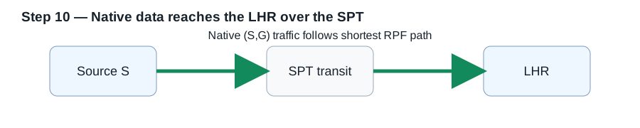
After receiving traffic over the RPT, the LHR learns the source address. Depending on its policy, it may switch to a direct source tree.
Possible policies include:
- Switch after the first packet
- Switch when traffic exceeds a configured rate
- Remain permanently on the RPT
To switch, the LHR performs a unicast RPF lookup for S:
RPF interface for (S,G) = interface toward S
RPF neighbor for (S,G)  = next-hop router toward S
The LHR sends an (S,G) Join toward the source. This creates the shortest-path tree:
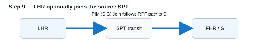
Source → shortest unicast-derived path → LHR → Receiver
The RPF path to S can differ substantially from the RPF path to the RP.
11. Pruning the Source from the RP Tree
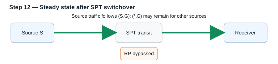
During SPT convergence, the LHR may briefly receive the same stream from both the RPT and SPT. After valid native traffic arrives on the SPT interface, the LHR no longer needs packets from source S through the RP.
It sends an (S,G,rpt) Prune toward the RP:
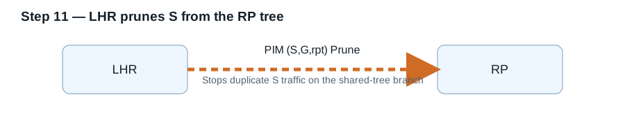
Stop forwarding source
Sdown this shared-tree branch for groupG.
The resulting state may resemble:
(*,G)
  Retained for unknown or other sources

(S,G)
  Incoming interface: toward S
  Outgoing interface: receiver LAN

(S,G,rpt)
  Prevents S from also arriving through the RPT
The RP can remain the discovery point for other ASM sources even though established source traffic bypasses it.
12. Multicast State Types
| State | Meaning | RPF lookup points toward |
|---|---|---|
(*,G) | Traffic from any source for group G | RP |
(S,G) | Traffic from source S for group G | Source |
(S,G,rpt) | Source-specific control state associated with the RP tree | RP |
The incoming interface can differ between (*,G) and (S,G) because one tree is rooted at the RP and the other is rooted at the source.
13. Join/Prune Processing
PIM Join/Prune messages are hop-by-hop messages addressed to a specific upstream neighbor.
A router’s multicast state contains:
(S,G)
  Incoming interface:
    Interface selected by RPF toward S

  Outgoing-interface list:
    Receiver branch 1
    Receiver branch 2
The router maintains its upstream Join while one or more downstream interfaces require the traffic.
When the last downstream interface is removed, the router can:
- Send an upstream Prune, or
- Stop refreshing the Join and allow the state to expire
PIM uses soft state. Joins must be refreshed periodically; they do not create permanent forwarding entries.
14. Reverse Path Forwarding
RPF ensures that multicast packets arrive from the expected upstream direction.
For (S,G) traffic:
Expected incoming interface = unicast next-hop interface toward S
For (*,G) state:
Expected upstream direction = unicast next-hop direction toward the RP
If a multicast packet arrives on an unexpected interface, it normally fails the RPF check and is discarded.
Important operational consequences:
- A missing route to
Sbreaks(S,G)forwarding. - A wrong route to the RP breaks
(*,G)tree construction. - Unicast route changes can alter multicast forwarding paths.
- Asymmetric routing is acceptable if the selected RPF path is valid.
- Equal-cost routes require consistent multicast RPF selection.
- A static multicast route may be needed when multicast must use a different upstream path from ordinary unicast traffic.
15. Designated Router Roles
PIM elects a Designated Router on a multi-access network.
The source-side DR:
- Detects directly connected multicast sources
- Creates source state
- Sends PIM Registers to the RP
The receiver-side DR:
- Processes IGMP membership
- Creates receiver-facing outgoing-interface state
- Sends PIM Joins upstream
The election normally prefers:
- Highest configured DR priority
- Highest IP address as a tie-breaker
16. PIM Assert
If multiple routers forward the same multicast stream onto one shared LAN, duplicate packets can occur. PIM Assert elects one forwarder for that LAN.
The election considers:
- Whether the route is associated with an SPT or RPT
- Route preference
- Route metric
- Router address as a tie-breaker
The losing router stops forwarding the affected multicast state onto that interface.
17. Control-Plane Summary
1.  Receiver → LHR: IGMP Membership Report for G
2.  LHR → RP direction: PIM (*,G) Join
3.  Source → FHR: multicast data to G
4.  FHR → RP: PIM Register containing multicast data
5.  RP → receiver: data forwarded down the shared tree
6.  RP → source direction: PIM (S,G) Join
7.  Native (S,G) data reaches the RP
8.  RP → FHR: PIM Register-Stop
9.  LHR → source direction: optional PIM (S,G) Join
10. Native data reaches the LHR over the SPT
11. LHR → RP direction: PIM (S,G,rpt) Prune
12. Source traffic now bypasses the RP
18. IGMP Versus PIM
Receiver ── IGMP Membership Report ──► LHR
LHR ── PIM (*,G) Join, hop by hop ──► RP
- IGMP communicates receiver interest to the local router.
- PIM communicates multicast-tree requirements between routers.
- The host does not send a PIM Join.
- The LHR does not normally send an IGMP Join to the RP.
Although engineers commonly say that a host “joins a multicast group,” the actual IGMP packet is formally a Membership Report.
18.1 IGMPv1 vs IGMPv2 vs IGMPv3
IGMP has three versions (IPv6 uses the equivalent MLD — MLDv1 ≈ IGMPv2, MLDv2 ≈ IGMPv3). Each generation kept the previous behavior and added capability, and the differences change how fast a group leaves, whether source filtering is possible, and how well IGMP snooping can see the membership.
| IGMPv1 (RFC 1112) | IGMPv2 (RFC 2236) | IGMPv3 (RFC 3376) | |
|---|---|---|---|
| Join | Membership Report | Membership Report | Membership Report with source lists |
| Leave a group | Silent — stop reporting; the group times out (minutes) | Leave Group message to 224.0.0.2, prompting a Group-Specific Query | State-change report altering the INCLUDE/EXCLUDE list |
| Leave latency | minutes (up to ~3× the query interval) | seconds (Leave + Group-Specific Query) | seconds, and can drop a single source |
| Query types | General Query only | + Group-Specific Query | + Group-and-Source-Specific Query |
| Querier election | not in IGMP — left to the routing protocol/PIM DR | lowest IP address on the subnet wins | lowest IP address (as v2) |
| Source filtering | none (any source) | none (any source) | yes — INCLUDE/EXCLUDE source lists per group |
| Enables SSM? | no | no | yes — Source-Specific Multicast (232.0.0.0/8) with no RP |
| Report is sent to | the group address G | the group address G | 224.0.0.22 (all IGMPv3 routers) |
| Report suppression | yes (one host answers per group) | yes | no — every host reports independently |
| Report message type | 0x12 | 0x16 (+ 0x17 Leave) | 0x22 (one report can carry many group records) |
The behaviors worth internalizing:
- Leave latency is the v1→v2 story. IGMPv1 has no leave message: a host simply stops answering queries, and the router only ages the group out after several missed query intervals — minutes of traffic sent to a LAN nobody wants. IGMPv2’s Leave Group (to all-routers
224.0.0.2) makes the router fire a Group-Specific Query; if no other member answers within the Max-Response window, the group is pruned in seconds. That single improvement is why v1 is effectively obsolete. - Source filtering is the v3 story, and it unlocks SSM. Only IGMPv3 lets a host say “group G, but only from source S” (INCLUDE) or “everything except S” (EXCLUDE). That is the receiver-side signal SSM (
232.0.0.0/8) needs: the last-hop router builds(S,G)state straight toward the source with no RP and no shared tree — the entire Register/RP machinery in this post simply doesn’t run for SSM. - v3 dropped report suppression, which is a gift to snooping. In v1/v2, a host that hears another host’s report for the same group stays quiet, so an IGMP-snooping switch sees only one reporter per group. IGMPv3 removes suppression — every interested host reports — so the switch (and any IGMP-snooping querier) sees the full per-port membership, which is exactly what constraining multicast to only the right ports needs.
- Querier election differs at v1. IGMPv1 has no querier election of its own — the multicast routing protocol (the PIM DR) picks who queries. IGMPv2 introduced the IGMP-level election: lowest IP address on the segment becomes the querier, with an Other-Querier-Present timer for failover. v3 keeps the v2 rule.
- Versions negotiate down. If any older host or router is present on a segment, IGMPv3 falls back to v2 (and v2 to v1) behavior for that group — losing source filtering in the process. Pin the version explicitly where SSM matters, and remember that a lone legacy device can silently disable v3 features for the whole segment.
A practical reminder tying back to the earlier sections: IGMP only ever runs between hosts and their first-hop router — it never builds the router-to-router tree. Everything from section 4 onward (the (*,G)/(S,G) joins, Register, RP) is PIM, driven by the membership IGMP reports to the DR.
18.2 IGMP snooping, packet by packet
How a switch turns those IGMP messages into per-port forwarding state — step through ten packets on a five-port switch (querier on p1, source on p2, three receivers): the General Query that finds the router port, two joins building the group table, data replicated to exactly the member ports, and the full normal-leave sequence — Leave, Group-Specific Queries, timeout, removal:
18.3 Fast leave (immediate leave)
Steps 6–9 of the walkthrough above are deliberately slow: when Receiver A leaves, the switch keeps forwarding to p3 while Group-Specific Queries check whether anyone else still listens there, and removes p3 only after the last-member timeout. Fast leave (Cisco calls it immediate leave) skips all of that: the switch removes the port from the group the moment the Leave arrives.
| Normal leave (walkthrough steps 6–9) | Fast leave | |
|---|---|---|
Receiver A sends Leave on p3 | Leave received | Leave received |
| Switch reaction | Group-Specific Queries; keep forwarding while waiting for reports | Remove p3 from the group immediately |
Traffic to p3 stops | after no response and the last-member timeout (seconds) | instantly |
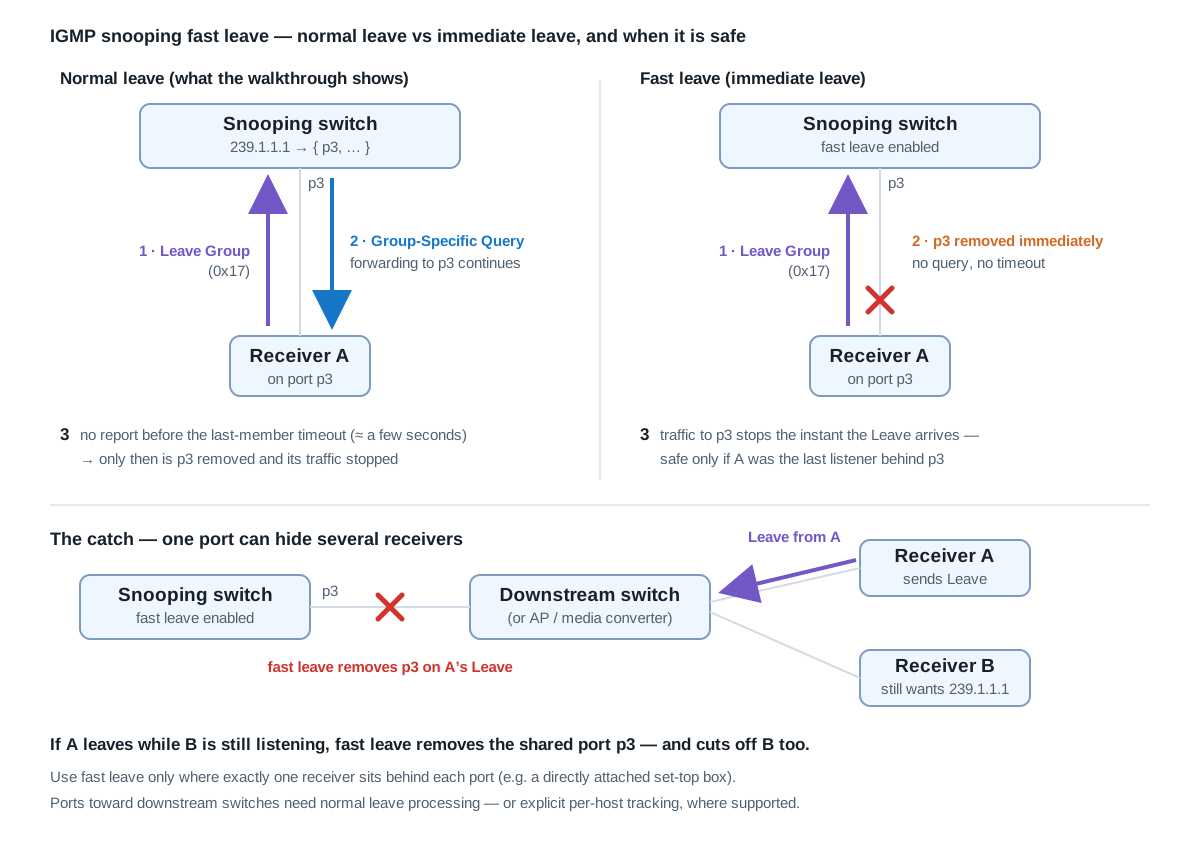
The catch: a port is not a receiver. The whole reason normal leave waits is that one switch port may lead to several hosts:
Snooping switch ── p3 ── downstream switch ──► Receiver A
                                          └──► Receiver B
If A leaves while B still wants the same group, fast leave removes the shared port p3 — cutting off both. B never sent a Leave, but its traffic stops anyway, and it stays dark until the next periodic General Query prompts it to report again — up to a full query interval (typically minutes) of outage.
The rule of thumb: enable fast leave only where exactly one receiver sits behind each port — the classic case being a directly attached IPTV set-top box, which is exactly why the knob exists: channel zapping wants sub-second leave latency, and an STB port has exactly one host behind it.
ip igmp snooping vlan 10 immediate-leave ! Cisco IOS
Ports toward downstream switches, APs, or hubs need normal leave processing — unless the switch explicitly supports safe fast leave through per-host tracking (often called explicit tracking, built on IGMPv3’s independent per-host reports from section 18.1), which lets it remove the port only when the last tracked host behind it has left.
19. Troubleshooting Order
When PIM-SM traffic is not reaching a receiver, verify:
- The receiver sent the correct IGMP report.
- The LHR learned local group membership.
- The LHR has the correct RP mapping for
G. - A
(*,G)Join is traveling toward the correct RPF neighbor. - The source-side DR detects the source.
- The FHR sends Registers to the correct RP.
- The RP has both source and receiver state.
- RPF checks succeed toward the RP and source.
- The outgoing-interface lists contain the required branches.
- Access lists, boundaries, or firewalls are not blocking IGMP, PIM, or multicast data.
- SPT switchover and
(S,G,rpt)pruning are behaving as intended.
20. Anycast RP for RP Redundancy
A single RP is both a single point of failure and a scaling bottleneck. Anycast RP removes both by giving several physical RPs the same RP address — a shared loopback advertised into the IGP from every member. Unicast routing then steers each first-hop router to the nearest RP, and each receiver’s shared tree terminates on whichever RP is nearest it.
20.1 The problem Anycast RP must solve
That “nearest RP” behavior creates a state-synchronization requirement. Unicast routing decides which RP a given first-hop router registers to, while receivers on the other side of the network join toward a different physical RP. Without a mechanism for the RP-set members to learn about sources registered to a peer, an (S,G) known only to RP1 is never pulled by receivers whose shared tree terminates on RP2.
20.2 Three ways to synchronize the RP set
1. MSDP (the original — RFC 3446). RPs peer over TCP/639 and exchange Source-Active (SA) messages carrying active (S,G) plus the RP originator-ID. Loop prevention is peer-RPF against the originator-ID — which is why each RP needs a unique loopback separate from the anycast address.
interface Loopback0
 ip address 10.0.0.1  255.255.255.255   ! anycast RP, advertised by IGP from both
interface Loopback1
 ip address 10.0.0.11 255.255.255.255   ! unique RP-ID
!
ip pim rp-address 10.0.0.1
ip msdp peer 10.0.0.12 connect-source Loopback1
ip msdp originator-id Loopback1
2. PIM Anycast-RP (RFC 4610) — no MSDP at all. The RP that receives a Register re-encapsulates and forwards it to every other member of the configured RP set, rewriting the outer source to its own RP-ID. Peers see a Register whose source is a known RP-set member and do not re-forward it — that is the loop prevention. State sync is inherent to the Register path: no separate protocol, no TCP session, no SA cache.
! IOS / NX-OS
ip pim rp-address 10.0.0.1
ip pim anycast-rp 10.0.0.1 10.0.0.11
ip pim anycast-rp 10.0.0.1 10.0.0.12    ! list every member, including self
3. Phantom RP (Bidir). Not really anycast — the RP address is unrouted and reachable only via longest match (a /30 on the primary, a /29 on the backup). Bidirectional PIM keeps no source state, so there is nothing to synchronize and MSDP is meaningless here.
20.3 Per-device configuration (RFC 4610)
The 10.0.0.11 and 10.0.0.12 addresses are the RP-set members, each identified by its unique per-router address — not the shared anycast address:
ip pim anycast-rp <anycast-address> <rp-set-member-address>
                   └─ 10.0.0.1 ─┘     └─ 10.0.0.11 / .12 ─┘
RP1:
interface Loopback0
 ip address 10.0.0.1  255.255.255.255   ! anycast, identical on both
interface Loopback1
 ip address 10.0.0.11 255.255.255.255   ! unique to RP1
!
ip pim rp-address 10.0.0.1
ip pim anycast-rp 10.0.0.1 10.0.0.11    ! itself
ip pim anycast-rp 10.0.0.1 10.0.0.12    ! peer
RP2:
interface Loopback0
 ip address 10.0.0.1  255.255.255.255
interface Loopback1
 ip address 10.0.0.12 255.255.255.255   ! unique to RP2
!
ip pim rp-address 10.0.0.1
ip pim anycast-rp 10.0.0.1 10.0.0.11
ip pim anycast-rp 10.0.0.1 10.0.0.12
The anycast-rp lines are byte-identical on every member — only Loopback1 differs, which makes the configuration easy to template.
Why you list yourself. The local entry is not decoration. It does two things: it tells the router “I am a member of this set,” and it supplies the source address used when re-encapsulating a Register to the other members. Omit it and the router either will not participate or forwards with the wrong source, which breaks the peer’s loop check.
Two routing requirements:
Loopback0(10.0.0.1) must be advertised into the IGP by every member. The unicast metric decides which RP a given router lands on.Loopback1(.11/.12) must also be advertised and be uniquely reachable — Register forwarding is unicast between RP-IDs, so if an RP-ID is not routable the sync silently fails.
20.4 When you still want MSDP — and when you cannot use it
RFC 4610 is an intra-domain mechanism; it assumes a single administrative RP set. Reach for MSDP when:
- Inter-domain / inter-AS PIM-SM. Anything crossing a trust boundary still wants MSDP, with SA filters, mesh groups, and
ip msdp sa-limit. - Policy control. MSDP gives you SA filtering, redistribution lists, and rate limiting. RFC 4610 gives none of that — every Register is forwarded to every member.
- Interop with an existing MSDP-based design you do not want to migrate.
You cannot use MSDP for:
- IPv6. MSDP was never defined for v6. PIM6 anycast RP is RFC 4610 or embedded RP (RFC 3956) only.
- Bidir, per above.
- SSM — no RP, so the question does not arise.
20.5 Practical bias for a data-center fabric
For an EVPN/VXLAN underlay running PIM-SM for BUM replication, RFC 4610 anycast RP on the spines is the cleaner choice: one configuration line per member, no TCP sessions to babysit, no SA cache to size, and no peer-RPF surprises when the underlay reconverges. MSDP’s extra machinery buys policy knobs you do not need inside a single-admin underlay. (This is the same choice the VXLAN EVPN Architecture multicast-underlay section reaches for.)
The one gotcha is scale: Register forwarding is control-plane punted on every RP in the set, so a large RP set with a high source-churn rate multiplies the punt load. Two or three spines as RPs, not eight.
20.6 Verify
show ip pim anycast-rp          ! NX-OS — shows RP-set membership
show ip mroute <group>          ! (S,G) should appear on BOTH RPs
If (S,G) shows up on RP1 but only (*,G) on RP2, you have either missed a member in the RP set or the RP-ID is not reachable. Vendor syntax differs slightly — Arista puts it under router pim sparse-mode, Juniper uses anycast-pim with an rp-set stanza — but the two-address model (a shared anycast address plus a unique per-member RP-ID) is identical everywhere.
21. Multicast ECMP
Multicast ECMP uses multiple equal-cost routes by distributing multicast trees across different upstream paths. In conventional PIM multicast, a router generally selects one upstream path for each multicast tree, while different trees can use different paths.
This section covers native IP multicast with PIM-SM and SSM. Multicast carried inside tunnels (MVPN, VXLAN underlays) can involve additional load-balancing mechanisms. For how these rules interact with the DR and Assert elections on shared segments, see the companion post PIM DR, Assert, and Multicast ECMP.
21.1 The basic terms
ECMP means Equal-Cost Multipath: a router has several equally preferred routes toward an address. For multicast, these terms matter (the first five are the notation from section 1):
| Term | Meaning |
|---|---|
S | Source IP address |
G | Multicast destination group |
(S,G) | Traffic from one particular source to one group |
(*,G) | Shared-tree state for a group, independent of a particular source |
| RP | Rendezvous Point, the root of a shared tree |
| RPF interface / IIF | The expected incoming interface for multicast traffic |
| OIL / OIF list | The outgoing interfaces that need a copy of the traffic |
For example, (10.1.1.10, 232.1.1.1) identifies multicast traffic sent by 10.1.1.10 to group 232.1.1.1.
PIM uses routing information to build trees toward a source or RP. This information commonly comes from unicast routing, but a separate multicast routing topology can also supply it (RFC 7761).
21.2 Why multicast ECMP is different from unicast ECMP
With unicast, the typical decision is:
Which next hop should I use to send this packet toward its destination?
With multicast, there are two decisions:
Which upstream path should deliver this tree’s traffic to me?
Which downstream interfaces need a copy?
ECMP primarily affects the upstream selection. Replication serves the downstream receivers.
A multicast router can therefore have one incoming interface and several outgoing interfaces. Sending copies on those outgoing interfaces is normal multicast replication.
21.3 A concrete example
A diamond topology: the source S sits behind first-hop router R0, and R3 — the receiver-side router — has equal-cost paths toward S through R1 and R2. Suppose the receiver requests (S,G1), and R3’s multicast ECMP selection chooses R1:
- R3 learns that a local receiver wants
(S,G1). - R3 looks up the route toward
S. - R1 and R2 are both eligible equal-cost upstream neighbors.
- R3 selects R1 for this tree.
- R3 directs its PIM Join toward R1.
- The Join continues toward the source.
- Multicast data flows back along the established branch.
Join direction:    R3 → R1 → R0
Data direction:    R0 → R1 → R3 → Receiver
For another group, G2, R3 might select R2:
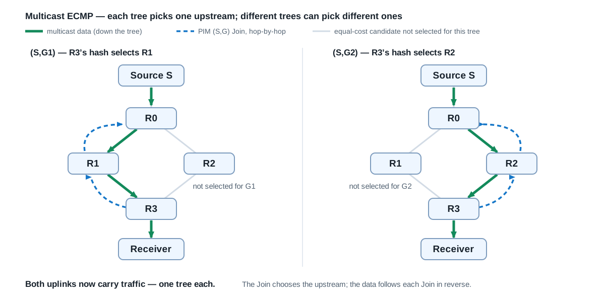
Both paths now carry traffic, with each tree using its selected upstream path. This is the basic multicast ECMP mechanism: distribute upstream Join choices, and the data follows those choices in reverse. RFC 2991 explains why per-tree — never per-packet — selection is the safe granularity when multipath meets RPF.
21.4 How the RPF check fits in
In the steady-state source-tree example, R3 records something like:
Multicast entry:     (S,G1)
Incoming interface:  link to R1
Outgoing interfaces: receiver-facing interface
When a packet arrives:
| Arrival interface | Expected result |
|---|---|
| From R1 | Passes the incoming-interface check |
| From R2 | Normally fails the RPF check for this tree |
The important detail: having two equal-cost routes does not automatically make both interfaces valid incoming interfaces for the same tree. The upstream Join selection and the expected incoming interface must agree — otherwise packets arrive through a path the router rejects. The actual PIM forwarding rules also account for shared trees and transitions between trees (RFC 7761, Section 4.2).
This is why an upstream router cannot simply alternate packets between R1 and R2 independently of downstream multicast state.
21.5 How the router selects a path
The selection method depends on the platform and configuration. Common approaches:
| Selection method | Consequence |
|---|---|
| Deterministic tie-break | Many or all trees may select the same upstream |
| Source-based hash | Groups from the same source tend to share an upstream |
| Source-and-group hash | Different groups from one source can select different upstreams |
| Hash incorporating next-hop identity | Mapping also depends on the candidate upstream neighbors |
Cisco documents source-based, source-and-group-based, and next-hop-aware multicast load splitting (IP Multicast Load Splitting across Equal-Cost Paths). Note that enabling unicast ECMP alone does not establish which multicast selection method is active — without ip multicast multipath, the RPF tie-break picks one path deterministically.
The three Cisco modes, interactive — six (S,G) trees hashed across three equal-cost next hops under each mode; press Fail next hop B to see how many trees move (and, for the non-next-hop-aware hashes, how even surviving selections can churn):
Consider one source sending four groups. An illustrative mapping:
| Stream | Source-only selection | Source-and-group selection |
|---|---|---|
(S,G1) | R1 | R1 |
(S,G2) | R1 | R2 |
(S,G3) | R1 | R2 |
(S,G4) | R1 | R1 |
With source-only selection, every stream has the same source input. Adding the group provides more opportunities to distribute traffic. These mappings are examples — a hash does not promise an even split.
21.6 One large stream usually stays on one path
Suppose there are two 10-Gbps upstream links and one 8-Gbps (S,G) stream. With conventional per-tree multicast ECMP, that stream selects one upstream link and the other carries none of it — the two links never become a 20-Gbps pipe for a single stream. (A 15-Gbps stream would not fit at all; that problem needs faster links, not a better hash.)
Now suppose there are four streams, each at 3 Gbps. If two select each path, each link carries 6 Gbps. Equal stream counts still do not guarantee equal bandwidth, though — take a different set of four streams, again two per path:
| Path | Streams | Total |
|---|---|---|
| R1 | 8 Gbps + 100 Mbps | 8.1 Gbps |
| R2 | 100 Mbps + 100 Mbps | 200 Mbps |
A hash distributes identifiers; it does not inherently measure traffic rates. Multicast ECMP is therefore most useful when there are enough independently selectable trees — Cisco describes this as load splitting across multicast states, not packets.
21.7 Shared trees and source trees can choose different paths
The routing lookup depends on the tree:
| Tree | Upstream lookup target |
|---|---|
Shared tree (*,G) | RP address |
Source tree (S,G) | Source address S |
In Any-Source Multicast, a receiver can initially receive traffic through the RP tree and later switch to a shortest-path tree toward S (the section 10 switchover). The equal-cost candidates toward the RP may differ from those toward S, so the selected incoming path can change during that switch.
Source-Specific Multicast joins (S,G) directly and does not require an RP for that delivery (RFC 7761, Section 4.8; RFC 4607).
21.8 “One upstream per tree” is a local rule
It does not mean an (S,G) uses only one link everywhere in the network:
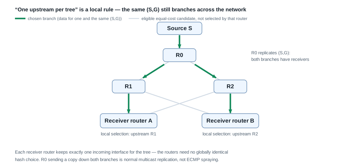
- Receiver router A selects R1 upstream.
- Receiver router B selects R2 upstream.
The source-side router can replicate the same stream toward both R1 and R2 because both branches have receivers. Each receiver router still has one selected upstream for that tree — across the network, the tree naturally branches.
Likewise, the routers do not need to make an identical hash choice globally. Each router selects its own eligible upstream, and its Join builds the corresponding branch.
21.9 What happens when a path fails?
If R3’s selected upstream path through R1 fails, R3 must select another eligible upstream and update its multicast state. Conceptually:
Before:  (S,G1) arrives through R1
         Failure detected
         New upstream selected: R2
         Join established through R2
After:   forwarding resumes through R2
Interruption depends on failure detection, route convergence, PIM processing, and forwarding-table updates. An available equal-cost route alone does not guarantee lossless failover.
Some implementations provide make-before-break behavior and controls for redistributing Joins (Juniper: Configuring PIM Join Load Balancing, PIM make-before-break example). Whether existing trees move when a path returns also depends on the implementation and configuration — the interactive figure in section 21.5 shows the churn difference between the hash modes on a failure.
21.10 How to troubleshoot it
For a particular (S,G), work through these questions:
- Which address is the RPF lookup using? The source or the RP?
- Are multiple eligible equal-cost routes actually present? Inspect the routing information used by multicast.
- Which upstream did multicast select? Check the tree’s RPF neighbor and incoming interface.
- Does the Join follow that upstream? Inspect PIM neighbors and multicast state hop by hop.
- Where do the packets actually arrive? Compare interface counters or captures with the selected incoming interface.
- Are downstream interfaces present? Passing RPF is insufficient if no interface needs the traffic.
- Does the selection method fit the traffic? One source with many groups can distribute poorly under source-only selection.
- Are you expecting equal bandwidth from unequal streams? Check traffic rates, not just tree counts.
The key relationship to remember:
Multicast ECMP selects upstream branches for trees; PIM Joins establish those branches; RPF validates incoming traffic; replication delivers copies downstream.
22. Key Idea
PIM-SM separates source discovery from optimized forwarding:
- The RP provides a stable meeting point for receivers and previously unknown ASM sources.
- The shared tree allows traffic to begin without receivers knowing the source in advance.
- Native
(S,G)trees eliminate Register encapsulation. - An optional SPT lets established traffic bypass the RP and follow the best source-to-receiver path.