
RoCE QoS Concepts and Packet Examples
There are many docs that use different terms on QoS — PCP vs CoS, for example, are in fact the same thing. This doc consolidates the QoS concepts and terminology behind RoCEv2 deployments, with decoded packet examples.
It is the concepts companion to two other posts on this blog: End-to-End RoCEv2 Configuration: Cisco Nexus, Cumulus Linux, and ConnectX is the configuration guide that turns these concepts into working templates, and RDMA Performance Tuning covers tuning and packet-loss troubleshooting once the fabric is up.
1. End-to-end QoS pipeline
A simplified forwarding pipeline is:
Application/RNIC marks packet
        ↓
DSCP in IP header or PCP in VLAN tag
        ↓
Switch trusts and classifies the marking
        ↓
DSCP/PCP → internal Traffic Class (TC)
        ↓
        ├──→ ingress Priority Group (PG) and buffer
        └──→ egress queue
                  ↓
           scheduler (for example, DWRR)
                  ↓
           WRED/ECN congestion handling
                  ↓
           physical interface
For a lossless RoCE class, PFC can protect the ingress priority group, while ECN/CNP controls congestion end to end.
The configuration-guide counterpart of this diagram — a concrete packet walk with the Cumulus one-command profile and the SONiC CONFIG_DB rendering — is section 1.5 of the RoCEv2 end-to-end post.
2. DSCP, ToS, CS, PCP and CoS
DSCP and ECN
The modern IPv4/IPv6 Differentiated Services field is eight bits:
  7   6   5   4   3   2   1   0
+-----------------------+-------+
|     DSCP (6 bits)     |  ECN  |
+-----------------------+-------+
- DSCP — Differentiated Services Code Point is a Layer-3 classification marking with values from 0 through 63.
- ECN is a two-bit congestion-signaling field.
- The complete eight-bit field is still commonly called the ToS byte, although ToS is the historical IPv4 name.
If ECN is zero:
ToS byte = DSCP << 2 = DSCP × 4
Examples:
| DSCP | Name | ToS byte with ECN 0 |
|---|---|---|
| 0 | CS0 / Best Effort | 0 |
| 8 | CS1 | 32 |
| 16 | CS2 | 64 |
| 24 | CS3 | 96 |
| 26 | AF31 | 104 |
| 32 | CS4 | 128 |
| 46 | EF | 184 |
| 48 | CS6 | 192 |
Therefore:
DSCP 24 is not ToS 24.
DSCP 24 produces a ToS/DS byte of 96 when ECN is zero.
Class Selector (CS)
Class Selector values preserve compatibility with the older IP Precedence scheme:
CS number × 8 = DSCP value
Thus:
CS3 = DSCP 24
DSCP 26 is AF31, not CS3.
ECN values
| Bits | Name | Who sets it | Meaning |
|---|---|---|---|
00 | Not-ECT | Sender | This flow does not support ECN at all |
01 | ECT(1) | Sender | ECN-Capable Transport — “you may mark me instead of dropping me” |
10 | ECT(0) | Sender | ECN-Capable Transport — same promise as ECT(1) |
11 | CE | Congested switch | Congestion Experienced — the actual congestion signal |
A common misreading is to interpret these as congestion levels — 01 mild, 10 worse, 11 severe. That is not how the field works. The two bits encode only two facts: whether the sender supports ECN (the ECT codepoints, set at transmission time before any congestion exists) and whether some switch on the path experienced congestion (CE). There is exactly one congestion signal, CE, and it is binary — there is no “low” or “high” congestion encoding.
Walking through each value:
00Not-ECT — the sender declared no ECN support. A congested switch is not allowed to mark this packet; its only congestion action is to drop it. This is why a RoCE sender that forgets to set ECT loses packets under congestion even on a correctly configured fabric: WRED selects the packet, can’t mark it, and discards it instead.01ECT(1) and10ECT(0) — functionally equivalent for classic ECN: both simply mean “ECN-capable.” Two codepoints exist for historical reasons (RFC 3168 reserved ECT(1) for a receiver-honesty experiment called the ECN nonce, later abandoned; RFC 9331 has since repurposed ECT(1) as the L4S identifier). In practice, RoCEv2/DCQCN senders mark data packets ECT(0) — binary10— and that is the value to expect in a capture.11CE — set by a congested switch when WRED/ECN selects an ECT packet (section 6). The sender never transmits CE, and once set, no downstream device clears it.
Your mental model for RoCEv2 should be a relay: the sender stamps ECT(0) at transmit time, a congested switch flips ECT(0) → CE while leaving DSCP untouched, and the receiving RNIC, on seeing CE, generates the CNP back toward the sender (section 10). So it is not that 11 “requests” a CNP in the packet itself — CE is a one-way mark on the forward data packet, and the CNP is a separate reverse-direction packet the receiver creates in response. (TCP uses the same CE mark but echoes it differently, via the ECE flag in the TCP header.)
PCP and CoS
PCP — Priority Code Point is the three-bit IEEE 802.1p field in an 802.1Q VLAN tag. Its values range from 0 through 7. The term CoS — Class of Service commonly refers to PCP.
| Property | DSCP | PCP/CoS |
|---|---|---|
| Layer | Layer 3 | Layer 2 |
| Header | IPv4/IPv6 | 802.1Q VLAN |
| Width | 6 bits | 3 bits |
| Range | 0–63 | 0–7 |
| Routable marking | Normally yes | Link/Layer-2 domain |
Do not confuse CS (Class Selector) with CoS (Class of Service).
Trust and mapping
A port may trust DSCP, trust PCP, or ignore incoming markings. External markings are mapped into an internal traffic class:
DSCP 24 ─┐
DSCP 26 ─┼→ TC 3 → PG 3 and Queue 3
PCP 3  ──┘
These relationships are configured policy. Neither DSCP 24 nor DSCP 26 inherently means TC, queue or priority 3.
SONiC tables commonly involved include:
DSCP_TO_TC_MAP
DOT1P_TO_TC_MAP
TC_TO_QUEUE_MAP
TC_TO_PRIORITY_GROUP_MAP
MAP_PFC_PRIORITY_TO_QUEUE
PORT_QOS_MAP
Useful live checks:
sudo sonic-cfggen -d --print-data | jq '.DSCP_TO_TC_MAP'
sudo sonic-cfggen -d --print-data | jq '.DOT1P_TO_TC_MAP'
sudo sonic-cfggen -d --print-data | jq '.TC_TO_QUEUE_MAP'
sudo sonic-cfggen -d --print-data | jq '.TC_TO_PRIORITY_GROUP_MAP'
sudo sonic-cfggen -d --print-data | jq '.PORT_QOS_MAP'
The RoCEv2 end-to-end post’s section 1.5 walks the full SONiC pipeline with these tables in place, plus the egress-stage tables (WRED_PROFILE, SCHEDULER) not repeated here.
DSCP 24 versus DSCP 26 for RoCE
There is no universal RoCEv2 DSCP. Designs commonly use values such as:
DSCP 24 = CS3
DSCP 26 = AF31
The correct value is the value configured consistently on the RNICs and every switch in the path. A typical policy is:
Site-selected RoCE DSCP → TC 3 → PG 3 / Queue 3 → PFC priority 3
3. Internal traffic classes, priority groups and queues
- Traffic Class (TC): internal classification used by the switch.
- Priority Group (PG): generally an ingress-buffer object.
- Queue: generally an egress-buffer and scheduling object.
Example:
RoCE DSCP
    ↓
TC 3
    ├──→ PG 3 → lossless ingress buffer and PFC
    └──→ Queue 3 → egress scheduling and ECN
Many RNIC queue pairs can share one network queue:
QP 101 ─┐
QP 102 ─┼→ DSCP 24 → TC 3 → switch Queue 3
QP 103 ─┘
The full DSCP → switch-priority → queue map, and the RoCE 3-queue preset
The definitions above are abstract; the mapping becomes concrete once you see a real preset end to end. The diagram shows both layers at once — the default trusted-DSCP classification on top, and the NVIDIA Cumulus RoCE preset on the bottom:
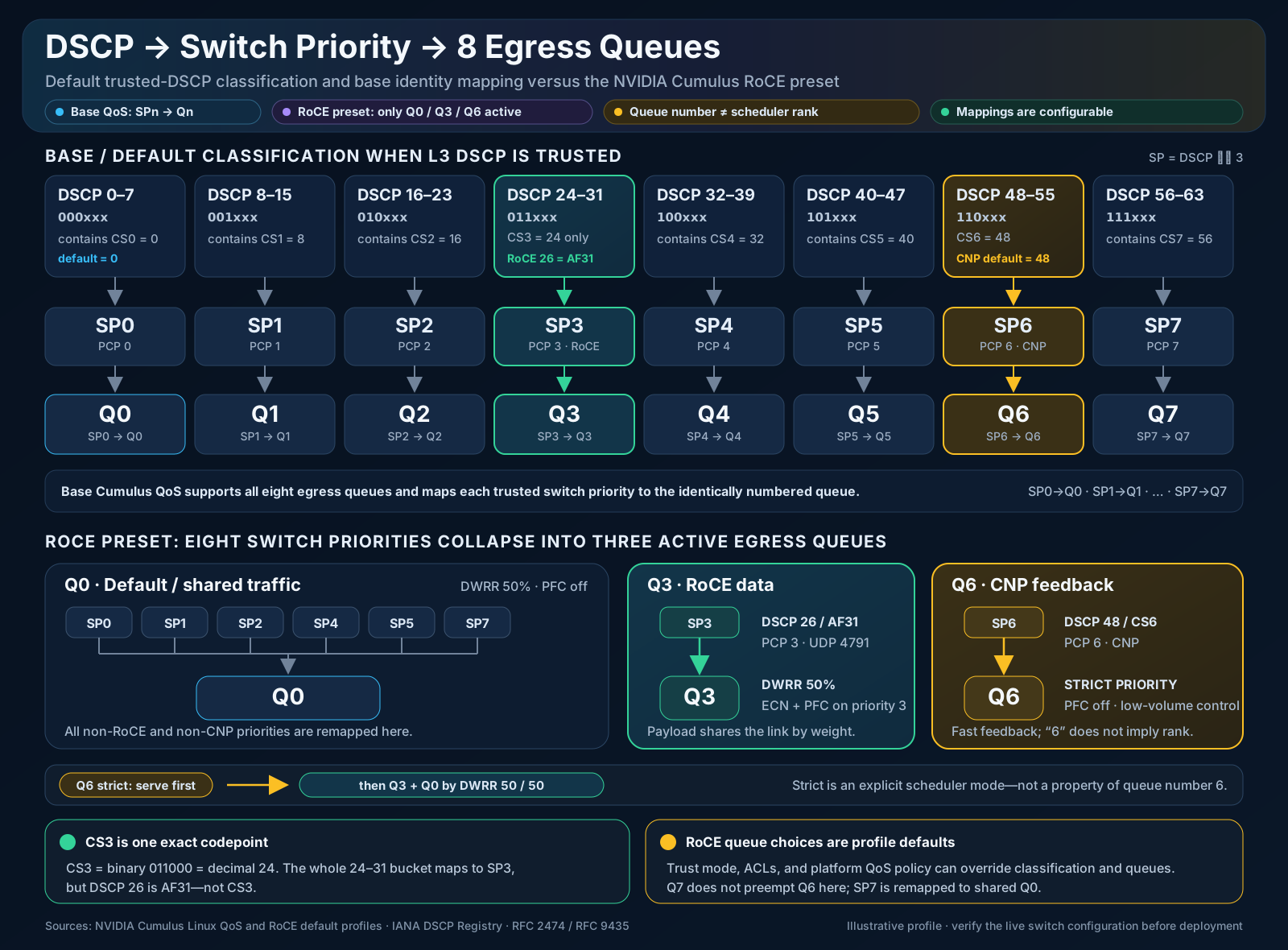
Top — the default identity mapping. When a port trusts L3 DSCP, each eight-value DSCP bucket resolves to one internal switch priority (SP). Switch priority is NVIDIA/Cumulus’s name for the internal priority level that this post’s other sections call a traffic class — the platform-internal handle a marking resolves to, which then selects a queue. The default rule is just the top three DSCP bits:
SP = DSCP >> 3 (DSCP 24–31 → SP3, DSCP 48–55 → SP6, …)
Each switch priority then maps to the identically numbered egress queue — SP0 → Q0, SP1 → Q1, … SP7 → Q7. All eight queues exist and are usable.
Bottom — the RoCE preset collapses eight priorities into three active queues. A RoCE profile does not need eight queues; it needs a lossless data class, a fast control class, and one bucket for everything else:
| Queue | Carries | Switch priorities mapped in | Scheduling | PFC / ECN |
|---|---|---|---|---|
| Q0 | default / everything else | SP0, 1, 2, 4, 5, 7 | DWRR ~50% | lossy, no PFC |
| Q3 | RoCE data (DSCP 26 / AF31) | SP3 | DWRR ~50% | ECN + PFC on priority 3 |
| Q6 | CNP feedback (DSCP 48 / CS6) | SP6 | strict priority | lossy, no PFC |
The scheduler serves Q6 strict-priority first — CNP is low-volume and latency-critical, and a delayed congestion signal defeats the whole feedback loop of section 10 — then splits the remainder between Q3 and Q0 by DWRR, here 50/50. That is exactly the two-part scheduler of sections 4–5: a strict-priority class on top, bandwidth remaining percent sharing beneath it.
Three precision points this picture pins down — each an instance of the post’s recurring warning not to read meaning into a number:
- A queue number is not a scheduler rank. Q6 is not served ahead of Q3 because 6 > 3; it is served first only because it is explicitly configured strict priority. The strict CNP queue’s index is itself just convention — this Cumulus preset uses Q6, while the Cisco Nexus example in section 5 uses Q7 for the same strict-priority role. And the highest-numbered queue here, Q7, is unused: SP7 is remapped down into the shared Q0. Rank comes from the scheduler configuration, never the queue index.
- CS3 is exactly DSCP 24 — one codepoint, not the bucket. The entire 24–31 range resolves to SP3, but only
011000= 24 is CS3. The common RoCE data value DSCP 26 is AF31 — it lands in SP3 / Q3 too, but it is a different codepoint, the same trap flagged in section 2. - Every arrow here is configurable policy, not silicon. Trust mode, ACLs, and the platform QoS profile can remap any DSCP, any switch priority, and any queue. This preset is a sensible default, not a hardware law — always verify the live switch configuration before relying on it.
4. DWRR
DWRR — Deficit Weighted Round Robin shares available egress bandwidth among queues according to configured weights.
Each queue receives byte-based transmission credit. If the next packet is larger than the current credit, unused credit is retained as a deficit and more credit is added in the next round. This gives better long-term byte fairness than a packet-count scheduler when packet sizes differ.
Example weights:
Queue 3:      60
Default queue: 40
When both queues are continuously backlogged, their long-term share is approximately 60/40. DWRR is normally work-conserving, so an active queue can borrow capacity left unused by an idle queue.
DWRR versus WRR
Plain WRR — Weighted Round Robin is the ancestor: each scheduling round, the scheduler dequeues a number of packets from each queue proportional to its weight. The unit of accounting is the packet, and that is exactly its weakness — packets are not the same size, so equal packet counts are not equal bandwidth.
The skew with mixed packet sizes:
Weights 1:1, both queues always backlogged

Queue A: 9000-byte jumbo frames  ┐   WRR serves one packet each per round
Queue B: 1500-byte packets       ┘

Bytes per round:  A = 9000, B = 1500
Actual bandwidth: A ≈ 86%,  B ≈ 14%   ← configured as 50/50
DWRR fixes this by accounting in bytes. Each round, a queue’s credit counter is increased by its quantum (proportional to its weight), a packet is sent only when the accumulated credit covers its size, and unused credit is carried forward as the deficit. Over time, each queue’s byte share converges to its configured weight regardless of the packet-size mix.
| Aspect | WRR | DWRR |
|---|---|---|
| Unit of accounting | Packets per round | Bytes (quantum + deficit counter) |
| Fairness with mixed packet sizes | Skewed toward large-packet queues | Byte-accurate long-term shares |
| Extra state per queue | Weight only | Weight plus a deficit counter |
| Where you meet it | Legacy or simple schedulers | Modern data-center ASICs |
This distinction matters for RoCE fabrics: RDMA data flows tend to be streams of full-MTU packets while other traffic mixes sizes, so a packet-count scheduler would quietly hand the RoCE queue more than its configured share. In practice the difference is mostly historical vocabulary — what data-center switch CLIs call “WRR” or “DWRR” today is almost always deficit-based byte scheduling underneath.
DWRR versus related functions
| Function | Purpose |
|---|---|
| DWRR | Relative bandwidth sharing during contention |
| Strict priority | Serve a queue ahead of ordinary queues |
| Shaper | Enforce a maximum scheduling rate |
| Policer | Enforce a rate by dropping or remarking excess traffic |
| ETS | Express bandwidth allocation among DCB traffic classes |
5. bandwidth remaining percent
Consider:
policy-map type queuing ROCE-EGRESS
  class type queuing c-out-8q-q7
    priority level 1

  class type queuing c-out-8q-q3
    bandwidth remaining percent 60

  class type queuing c-out-8q-q-default
    bandwidth remaining percent 40
bandwidth remaining percent 60 means:
After strict-priority traffic is served, queue 3 receives a 60% relative share of the remaining bandwidth when the eligible queues contend for capacity.
It does not cap queue 3 at 60% of the interface rate.
On a 100 Gbps interface:
| Strict-priority use | Remaining | Queue 3 at 60% | Default at 40% |
|---|---|---|---|
| 0 Gbps | 100 Gbps | ~60 Gbps | ~40 Gbps |
| 20 Gbps | 80 Gbps | ~48 Gbps | ~32 Gbps |
| 50 Gbps | 50 Gbps | ~30 Gbps | ~20 Gbps |
These allocations apply when both remaining-bandwidth queues are backlogged. If the default queue is idle and strict-priority traffic is absent, queue 3 can normally use nearly the full 100 Gbps.
In short:
bandwidth remaining percent = relative share under contention
                            ≠ maximum rate
6. WRED and ECN thresholds
Example:
class type queuing c-out-8q-q3
  bandwidth remaining percent 60
  random-detect minimum-threshold 150 kbytes
                maximum-threshold 3000 kbytes
                drop-probability 7
                weight 0
                ecn
Conceptually:
Queue occupancy

0 KB             150 KB                         3000 KB+
 |-----------------|--------------------------------|
 Forward normally   Increasing AQM probability       Strong congestion action
- Below 150 KB: no WRED/ECN action.
- Between 150 KB and 3000 KB: packet-selection probability grows from approximately zero toward 7%.
- At the upper threshold: configured probability is approximately 7%.
- Above the maximum threshold: classic WRED behavior is that the action probability jumps to 100% — every arriving packet in the class is dropped (or CE-marked when
ecnis configured). Tail drop still applies as the final backstop if the physical buffer fills.
With ecn:
- A selected ECN-capable packet is normally marked CE.
- A selected non-ECN-capable packet cannot be CE-marked and may be dropped.
A simplified interpolation within the configured range is:
P ≈ 7% × (occupancy − 150) / (3000 − 150)
Actual ASIC behavior is quantized by buffer cells and supported hardware thresholds.
drop-probability 7 does not mean that 7% of all packets are always dropped. It is the configured probability at the maximum threshold. With ECN enabled, selected ECN-capable packets are marked rather than immediately dropped.
weight 0 means the AQM decision closely follows current queue depth rather than a heavily smoothed historical average.
The two thresholds are not the queue’s allocated buffer size. They are congestion-action points. Buffer allocation, PFC thresholds and tail-drop limits are separate.
7. PFC
PFC — Priority Flow Control, standardized by IEEE 802.1Qbb, is a per-priority, hop-by-hop Ethernet pause mechanism.
Upstream device                   Congested downstream device
       |                                      |
       |------ priority 3 traffic ---------->|
       |                                      | Buffer reaches XOFF
       |<--------- PFC pause for P3 ----------|
       | Stop sending priority 3              |
       |                                      | Buffer drains to XON
       |<--------- PFC resume for P3 ---------|
       | Resume priority 3                    |
PFC pauses one or more priorities while allowing other priorities to continue. It does not allocate bandwidth and does not operate directly on DSCP. DSCP must first be mapped to an internal/PFC priority.
XOFF, XON and headroom
- XOFF: buffer threshold that triggers a PFC pause.
- XON: lower threshold at which transmission can resume.
- Headroom: buffer space needed for traffic already in flight after the pause is generated.
Conceptually:
XON < XOFF < drop threshold
PFC is link-local. A PFC frame is consumed by the directly connected neighbor and is not routed or forwarded through the fabric.
PFC direction
If Switch B is congested:
Switch A ------data------> Switch B
Switch A <-----PFC-------- Switch B
- Switch B increments PFC TX.
- Switch A increments PFC RX.
- Switch A pauses its selected egress priority toward Switch B.
PFC risks
PFC can cause:
- Pause propagation
- Head-of-line blocking
- Pause storms
- Victim-flow impact
- Cyclic buffer dependencies and deadlock
A PFC watchdog can detect a priority paused for too long and take recovery action, potentially sacrificing losslessness to restore network progress.
8. Example decoded PFC frame
This synthetic frame pauses priority 3:
Ethernet II
    Destination: 01:80:c2:00:00:01
    Source:      02:00:00:00:00:01
    Type: MAC Control (0x8808)

MAC Control
    Opcode: Priority-based Flow Control (0x0101)

Priority-based Flow Control
    Class Enable Vector: 0x0008
        Priority 0: Disabled
        Priority 1: Disabled
        Priority 2: Disabled
        Priority 3: Enabled
        Priority 4: Disabled
        Priority 5: Disabled
        Priority 6: Disabled
        Priority 7: Disabled

    Priority 0 pause quanta: 0
    Priority 1 pause quanta: 0
    Priority 2 pause quanta: 0
    Priority 3 pause quanta: 65535
    Priority 4 pause quanta: 0
    Priority 5 pause quanta: 0
    Priority 6 pause quanta: 0
    Priority 7 pause quanta: 0
Key fields:
Destination MAC:     01:80:c2:00:00:01
EtherType:           0x8808
MAC Control opcode:  0x0101
Class-enable vector: 0x0008
Priority 3 quanta:   0xffff
One pause quantum is 512 bit-times. At 100 Gbps, 65,535 quanta represent approximately 335.5 microseconds. A frame with priority 3 enabled and its quanta set to zero is a resume indication.
Useful Wireshark filter:
eth.type == 0x8808
PFC may be consumed in hardware and omitted from ordinary SPAN or host captures. Confirm it with hardware PFC TX/RX counters or a capable physical TAP.
9. DCBX
DCBX — Data Center Bridging Exchange uses LLDP extensions between directly connected devices to exchange DCB settings such as:
- PFC-enabled priorities
- ETS allocations
- Application priorities
- Willingness to accept advertised configuration
Server NIC ←── LLDP/DCBX ──→ Switch
DCBX exchanges configuration. It does not carry RoCE data, allocate switch buffers, or itself make Ethernet lossless.
For the deeper treatment — the IEEE 802.1Qaz versus CEE variants, the willing bit, why the end-to-end templates prefer static mode on over DCBX auto, and the lldpad-overriding-manual-settings pitfall — see section 1.4 of the RoCEv2 end-to-end post.
10. ECN, CNP and DCQCN
CNP — Congestion Notification Packet is RoCEv2 feedback telling a sender to reduce its transmission rate.
Sending RNIC             Congested switch             Receiving RNIC
     |                           |                           |
     |------ RoCEv2 data ------>|------ CE-marked data ---->|
     |                           |                           |
     |<------------------------- CNP -----------------------|
     | Reduce sending rate                                  |
The normal sequence is:
- A sender transmits an ECN-capable RoCEv2 packet.
- A congested switch marks the packet CE.
- The receiving RNIC detects CE.
- The receiving RNIC generates a CNP.
- The sending RNIC applies its congestion-control algorithm, such as DCQCN.
The switch normally marks CE; it does not generate the end-to-end CNP.
PFC versus ECN/CNP
| PFC | ECN/CNP |
|---|---|
| Hop-by-hop | End-to-end |
| Pauses a priority | Reduces source rate |
| Fast local protection | Congestion-control feedback loop |
| Can affect many flows/QPs | Can identify an affected QP/context |
| Emergency brake | Primary congestion-control mechanism |
A desirable threshold order is:
ECN begins before PFC XOFF
PFC XOFF occurs before tail drop
The goal is for ECN/CNP to slow senders before PFC is frequently required.
11. Example decoded CNP packet
This is a synthetic RoCEv2 CNP from receiver 10.0.0.2 to sender 10.0.0.1:
Ethernet II
    Destination: 02:00:00:00:00:01
    Source:      02:00:00:00:00:02
    Type: IPv4 (0x0800)

Internet Protocol Version 4
    Source Address:      10.0.0.2
    Destination Address: 10.0.0.1
    Protocol: UDP (17)

User Datagram Protocol
    Source Port:      53921
    Destination Port: 4791

InfiniBand Base Transport Header
    Opcode: CNP - Congestion Notification Packet (0x81)
    Partition Key: 0xffff
    Destination Queue Pair: 0x001234
    Packet Sequence Number: 0x000000

RoCEv2 Congestion Notification
    Reserved: 00000000000000000000000000000000

Invariant CRC
    ICRC: [calculated value]
The defining identifiers are:
UDP destination port: 4791
BTH opcode:            0x81
UDP port 4791 alone is not sufficient because normal RoCEv2 data uses the same destination port.
Useful Wireshark filter:
udp.dstport == 4791 && infiniband.bth.opcode == 0x81
The exact dissector field name can vary by Wireshark version, and the infiniband.bth.* fields only exist when Wireshark is actually dissecting UDP port 4791 as RoCEv2 (modern versions do this by default). If the filter matches nothing on a capture that clearly contains RoCE traffic, force it via Analyze → Decode As → UDP port 4791 → InfiniBand.
The CE mark that triggered the CNP is on the forward data packet. The CNP is a newly generated reverse-direction control packet and does not need to carry the original packet’s CE marking.
12. Queue pairs
QP — Queue Pair is an RNIC communication endpoint consisting of:
Queue Pair
├── Send Queue (SQ)
└── Receive Queue (RQ)
Applications post work requests to these queues. Reliable QPs maintain transport state including QP numbers, packet sequence numbers, retry state, access permissions and connection information.
Every QP has a Queue Pair Number (QPN). The 24-bit Destination QP field in the Base Transport Header selects the destination RNIC context.
For two connected QPs:
Host A QP 0x001234                    Host B QP 0x005678

A → B packets: DestQP 0x005678
B → A packets: DestQP 0x001234
A QP is not a switch QoS queue. A system can have many QPs while a switch port normally has only a small number of hardware QoS queues.
CNP destination QP and rate control
If the sender receives:
CNP Destination QP: 0x001234
the protocol intent is to identify QP 0x001234 as the congestion-control target.
Ideally:
QP 0x001234 → reduce rate
Other QPs   → not directly rate-limited by this CNP
However, actual RNIC rate-control granularity may be:
- Per QP
- Per flow
- Per destination
- Per traffic class
- Per shared congestion-control context
- Per group of QPs sharing a hardware rate limiter
Therefore, the CNP provides QP-specific identification, but perfect performance isolation from all other QPs must not be assumed without verifying the RNIC model, firmware, driver and congestion-control implementation.
Other QPs may also be affected indirectly:
- They may share an RNIC scheduler.
- They may share the same switch queue and receive their own CE marks/CNPs.
- PFC pauses an entire priority and can temporarily stop all QPs mapped to it.
13. Putting everything together
A representative RoCEv2 congestion sequence is:
1. RNIC marks RoCE data with the site's selected DSCP.
2. Switch maps DSCP → TC → PG and queue.
3. DWRR/ETS schedules the RoCE egress queue.
4. Queue occupancy crosses the ECN minimum threshold.
5. Switch probabilistically marks packets CE.
6. Receiver RNIC sends CNP with BTH opcode 0x81.
7. CNP DestQP identifies the affected sender context.
8. Sender congestion control reduces its rate.
9. Ideally the queue drains before PFC is required.
10. If ingress pressure reaches XOFF, PFC pauses the priority hop by hop.
11. When the buffer drains below XON, transmission resumes.
12. Tail drop is the final protection if buffer limits are exceeded.
14. Key takeaways
DSCP is a Layer-3 marking.
PCP/CoS is a Layer-2 priority.
TC is an internal switch classification.
PG is generally an ingress-buffer concept.
Queue is generally an egress-buffer/scheduler concept.

DWRR provides relative bandwidth sharing under contention.
"Bandwidth remaining percent" is not a maximum rate.

WRED/ECN thresholds define congestion-action points, not buffer allocation.
ECN marks congestion; CNP carries feedback to the sender.

PFC pauses a whole priority on one link.
CNP can identify an affected QP, subject to RNIC implementation granularity.
15. Header reference: VLAN, IPv4/IPv6, TCP and UDP
The markings this document keeps referring to — PCP, DSCP, ECN, port 4791 — each live at a fixed offset in a specific header. This section shows exactly where.
The RoCEv2 encapsulation stack
A RoCEv2 packet on the wire is:
Ethernet [+ 802.1Q tag] / IPv4 or IPv6 / UDP (dst 4791) / IB BTH / payload / ICRC / FCS
The QoS-relevant bits by header:
| Field | Lives in | Exists when |
|---|---|---|
| PCP (CoS) | 802.1Q VLAN tag | Only when the frame is tagged |
| DSCP + ECN | IP header (DS field / Traffic Class) | Always |
| ECMP entropy | UDP source port | Always |
| CNP identification | BTH opcode + Destination QP | Always |
Ethernet frame and the 802.1Q VLAN tag
An IEEE 802.1Q VLAN tag is 4 bytes, inserted between the source MAC address and the original EtherType field. The tag itself is two 16-bit halves — the TPID and the TCI:
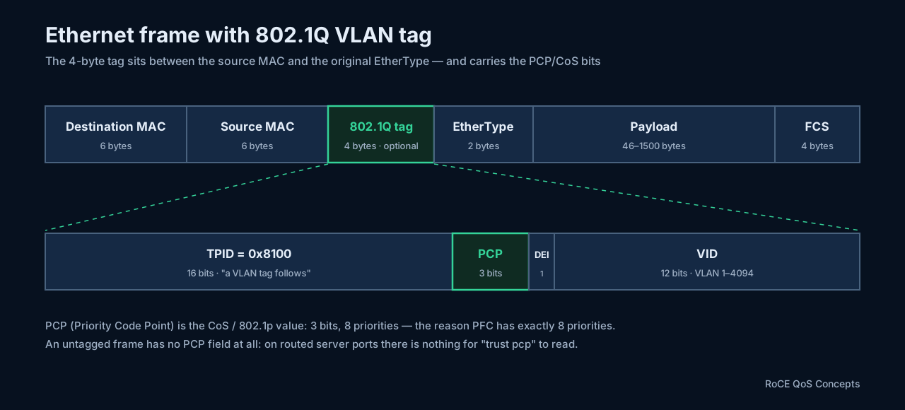
- TPID — Tag Protocol Identifier (
0x8100) occupies the position where EtherType would otherwise be; it announces “a VLAN tag follows.” The real EtherType (e.g.0x0800for IPv4) comes after the tag. - PCP — Priority Code Point (3 bits, 0–7): this is the CoS/802.1p value from section 2. Three bits is why Layer-2 priority has exactly 8 values, and why PFC has exactly 8 priorities.
- DEI — Drop Eligibility Indicator (1 bit): marks the frame as preferentially droppable under congestion. Rarely used in RoCE designs.
- VID — VLAN Identifier (12 bits): VLAN number, 1–4094 usable (0 means “priority tag only”, 4095 is reserved).
Frame-size consequence (excluding preamble and inter-frame gap):
Untagged maximum:      1518 bytes  (14 header + 1500 payload + 4 FCS)
One 802.1Q tag:        1522 bytes  (+4)
QinQ / double tag:     1526 bytes  (+8)
The practical consequence for QoS: an untagged frame has no PCP field at all. On routed (untagged) server ports there is simply nothing for trust pcp to read — which is why RoCE designs on L3 fabrics must trust DSCP, and why section 2 warns against mixing DSCP and PCP assumptions.
IPv4 header
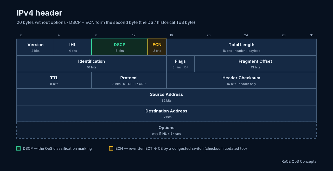
The header is normally 20 bytes (IHL = 5) and can grow to 60 bytes with options. Field by field:
| Field | Size | Purpose |
|---|---|---|
| Version | 4 bits | IP version; 4 for IPv4 |
| IHL | 4 bits | Header length in 32-bit words; minimum 5 = 20 bytes |
| DSCP | 6 bits | QoS marking — the classification value this whole document revolves around |
| ECN | 2 bits | Congestion signaling without dropping (section 2) |
| Total Length | 16 bits | Entire IPv4 packet: header + payload; maximum 65,535 bytes |
| Identification | 16 bits | Groups fragments belonging to the same original packet |
| Flags | 3 bits | Fragmentation control, including Don’t Fragment (DF) |
| Fragment Offset | 13 bits | Where a fragment sits in the original packet |
| TTL | 8 bits | Decremented by each router; packet dropped at 0 |
| Protocol | 8 bits | What follows the IP header |
| Header Checksum | 16 bits | Error check for the IPv4 header only |
| Source IP | 32 bits | Sender’s address |
| Destination IP | 32 bits | Receiver’s address |
| Options | Variable | Rarely used optional features |
The Protocol values worth memorizing:
Protocol = 6    → TCP
Protocol = 17   → UDP   (the RoCEv2 case)
Protocol = 1    → ICMP
A Total Length worked example:
IPv4 header:  20 bytes
TCP header:   20 bytes
Data:        100 bytes
------------------------
Total Length: 140 bytes
Three ties back to earlier sections:
- DSCP + ECN together are the second header byte — the DS field, historically the ToS byte. This is the byte dissected in section 2, and the reason
DSCP << 2appears whenever a tool wants the whole byte. A switch rewriting ECT → CE modifies only the low two bits — and must then update the header checksum. - The DF flag is what
ping -M dosets when validating MTU end to end. - The checksum is recomputed at every routed hop anyway, because TTL changes.
IPv6 note: IPv6 renames the DS byte to Traffic Class, but the internal layout is identical — the same 6-bit DSCP and 2-bit ECN. RoCEv2 over IPv6 uses it exactly the same way. IPv6’s fixed header is 40 bytes, and it adds a 20-bit Flow Label that some fabrics use as additional ECMP entropy.
TCP header
TCP is not part of the RoCEv2 stack — it appears here for contrast, and because the ECN story in section 2 referenced TCP’s echo mechanism. TCP provides, in one protocol: reliable delivery, ordered delivery, retransmission, flow control, congestion control, and connection establishment/termination. The minimum header is 20 bytes; with options it can reach 60 bytes.
Is RoCE traffic ever TCP? No — and this is worth stating plainly, because “RoCE runs over IP” invites the assumption that it could. RoCEv2 data is always UDP, destination port 4791; it is never TCP. The reason RoCE avoids TCP is not incidental: the RDMA transport already supplies its own reliability, in-order delivery, and retransmission in RNIC hardware (the BTH packet sequence numbers described below), so layering TCP’s byte-stream reliability and congestion control on top would only fight it. UDP is used purely as a routable envelope — it adds no reliability, it just gives each flow an IP/port five-tuple for ECMP hashing and L3 routing. (If you genuinely want RDMA carried over TCP, that is a different standard — iWARP — not RoCE. iWARP trades hardware simplicity for the ability to run on any lossy IP network; RoCEv2 instead demands a lossless or ECN-managed fabric, which is why this entire post exists.) So the only TCP you will see on a RoCE fabric is coexisting non-RDMA traffic — management planes, BGP, NVMe/TCP or iSCSI storage, tenant flows — and that is exactly what the default queue (Q0 in section 3) is there to absorb, held apart from the RoCE data queue and the CNP queue. In short: TCP is on the wire next to RoCE, never inside it.
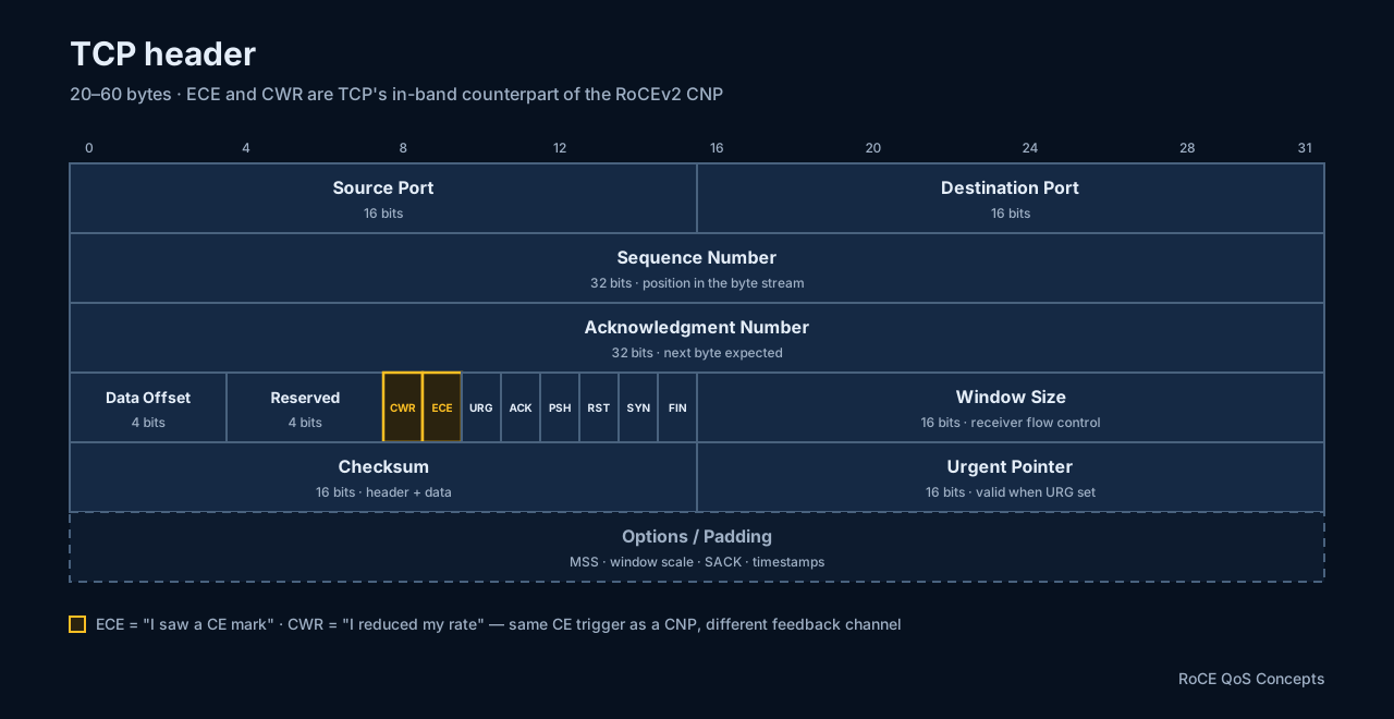
| Field | Size | Purpose |
|---|---|---|
| Source Port | 16 bits | Port used by the sending application |
| Destination Port | 16 bits | Port used by the receiving application |
| Sequence Number | 32 bits | Position of this data in the TCP byte stream |
| Acknowledgment Number | 32 bits | Next byte the receiver expects |
| Data Offset | 4 bits | Header length in 32-bit words (options make it variable) |
| Reserved | 4 bits | Reserved for future use |
| Flags | 8 bits | Connection and data-handling control bits |
| Window Size | 16 bits | How much more data the receiver will currently accept |
| Checksum | 16 bits | Covers TCP header and data |
| Urgent Pointer | 16 bits | Meaningful only when URG is set |
| Options | Variable | MSS, window scaling, timestamps, SACK |
Ports and the five-tuple. Ports identify applications: TCP 22 = SSH, 80 = HTTP, 443 = HTTPS, 179 = BGP. A TCP connection is identified by the five-tuple — source IP, destination IP, source port, destination port, protocol:
Source IP:        192.168.1.10
Source port:      51000
Destination IP:   10.10.10.20
Destination port: 443
Protocol:         TCP
This same five-tuple is what ECMP hashing uses to pick a fabric path — for TCP and for RoCEv2’s UDP alike.
Sequence and acknowledgment numbers. TCP treats application data as a continuous byte stream. If a sender transmits 500 bytes starting at sequence number 1000, the receiver replies with acknowledgment number 1500 — meaning “I have everything through byte 1499; send 1500 next.” Acknowledgments are always the next expected byte. This is TCP’s software equivalent of what BTH packet sequence numbers do for RoCE — implemented in the kernel, with far more per-packet overhead.
Flags:
| Flag | Meaning |
|---|---|
| SYN | Start a connection; synchronize sequence numbers |
| ACK | The acknowledgment field is valid |
| FIN | Close the connection gracefully |
| RST | Reset or reject the connection immediately |
| PSH | Deliver received data to the application promptly |
| URG | The Urgent Pointer is valid |
| ECE | ECN-Echo — receiver reports it saw a CE mark |
| CWR | Congestion Window Reduced — sender confirms it slowed down |
The ECE/CWR pair is TCP’s counterpart of the RoCEv2 CNP — but “counterpart” means functionally analogous, not the same header. A CNP never appears inside a TCP header; these are two independent congestion-feedback designs, in two different transports, that happen to share one trigger. It is easy to misread the analogy as “the UDP-based CNP is echoed in a TCP header,” which would make no sense — so it is worth separating the three moving parts.
The shared trigger lives in the IP header — not in TCP and not in UDP. The CE (Congestion Experienced) mark is the 2-bit ECN field of the IP header (section 2), set by a congested switch when WRED/ECN fires (section 6). Because it sits at L3, the same switch marks a TCP/IP packet and a RoCEv2 UDP/IP packet in the identical two bits. That common IP-layer trigger is the only thing the two mechanisms share.
The feedback path is where they diverge, because the transports are different:
- TCP has spare header bits and an ACK stream always flowing back, so it echoes the signal in-band, with no extra packet: the receiver sets ECE on the ACKs it was already sending; the sender then halves its congestion window and sets CWR on its next segment to confirm “I slowed down.”
- RoCEv2 rides UDP port 4791, whose header has no flag bits to echo anything — and RDMA is often a one-way write burst with no return traffic to piggyback on. So the destination RNIC (the notification point) must mint a brand-new packet: a CNP, itself a small RoCEv2 packet (a BTH carrying the CNP opcode
0x81), sent back to the source, which then cuts its rate via DCQCN (sections 10–11). There is no CWR-style confirmation — the sender simply slows.
| Aspect | TCP | RoCEv2 |
|---|---|---|
| Transport under IP | TCP | UDP :4791 |
| Where CE is set | IP-header ECN bits, by a congested switch | identical bits, same switch |
| First to react to CE | the receiver | destination RNIC (notification point) |
| Feedback vehicle | ECE flag on an ACK already going back | a whole new CNP packet in reverse |
| Sender’s confirmation | CWR flag on next data segment | none — sender just cuts rate (DCQCN) |
| Extra packets on the wire | zero (rides existing ACKs) | one CNP per event (rate-limited) |
That last row is the reason the RoCE preset in section 3 gives CNP its own strict-priority queue: TCP’s feedback is a free bit riding traffic that was going to flow anyway, whereas RoCEv2’s feedback is a real packet competing for bandwidth — and a congestion signal that arrives late breaks the DCQCN control loop. TCP never needs a dedicated queue for ECE, because ECE is not a packet at all.
The three-way handshake:
Client                                      Server

SYN, Seq=100        ---------------------->

                    <----------------------  SYN-ACK, Seq=500, Ack=101

ACK, Ack=501        ---------------------->

Connection established
Why does the acknowledgment become 101 when no data was sent? Because a SYN consumes one sequence number: initial sequence 100 + SYN = next expected 101. (FIN does the same at teardown.)
Window size and scaling. The advertised window is receiver flow control: with Window = 65,535, the sender may have at most that many unacknowledged bytes in flight. Since 16 bits caps the window at 64 KB — far too small for high-bandwidth, high-latency paths — modern TCP negotiates the Window Scale option at connection setup. Flow control (receiver capacity) is distinct from congestion control (network capacity, inferred from loss and ECN).
MSS — Maximum Segment Size. The largest TCP payload a host wants per segment, derived from the MTU:
IPv4:  1500 MTU − 20 IPv4 header − 20 TCP header = 1460-byte MSS
IPv6:  1500 MTU − 40 IPv6 header − 20 TCP header = 1440-byte MSS
TCP options (timestamps, SACK) reduce the usable payload further.
UDP header
UDP is the opposite philosophy: the header is always 8 bytes, four fields, and it adds addressing and nothing else.
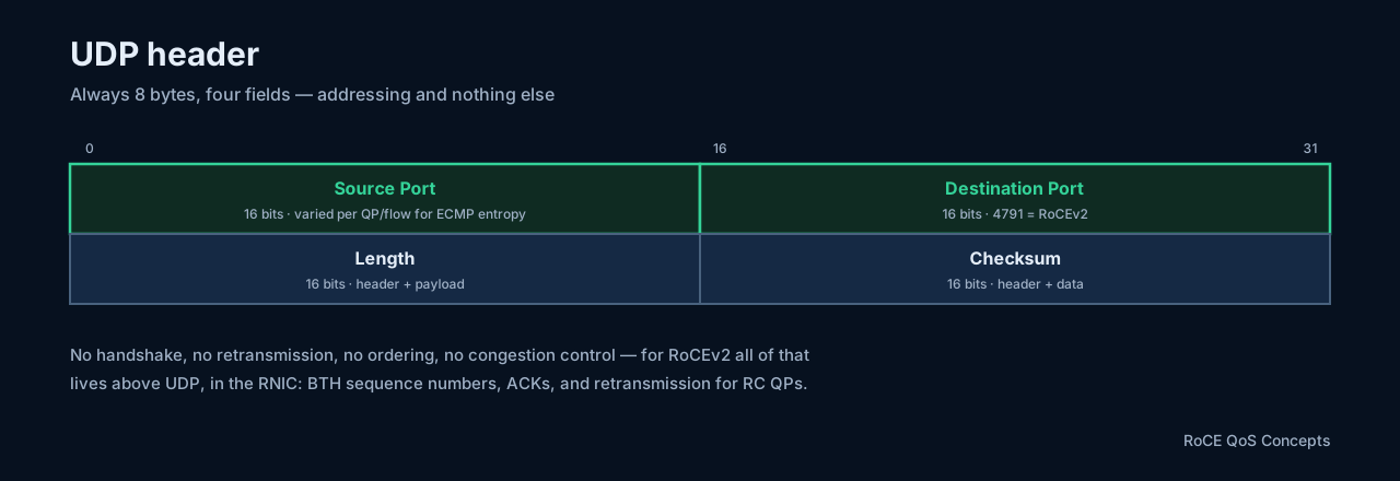
| Field | Size | Purpose |
|---|---|---|
| Source Port | 16 bits | Sending application’s port (may be 0 in IPv4) |
| Destination Port | 16 bits | Receiving application’s port |
| Length | 16 bits | UDP header + payload |
| Checksum | 16 bits | Detects corruption in header and data |
Length example: an 8-byte header plus 40 bytes of DNS data gives UDP Length = 48.
Common UDP ports:
UDP 53      DNS
UDP 67/68   DHCP
UDP 123     NTP
UDP 161     SNMP
UDP 4789    VXLAN
UDP 4791    RoCEv2
UDP itself provides no connection establishment, no delivery confirmation, no retransmission, no ordering, no flow control, and no congestion control. Applications that need those build them on top — QUIC implements reliability, encryption, and congestion control above UDP in userspace, and RoCEv2 does the same in hardware: BTH sequence numbers, ACKs, and retransmission for RC QPs live in the RNIC, not the kernel.
Two RoCEv2-specific notes:
- Destination port 4791 is what makes a packet RoCEv2 at all.
- The source port is not a service identifier — RNICs vary it per QP/flow deliberately so five-tuple ECMP hashing spreads flows across fabric paths. Two QPs between the same host pair can take different spine paths because of this field alone.
TCP versus UDP
| Feature | TCP | UDP |
|---|---|---|
| Header size | 20–60 bytes | 8 bytes |
| Connection-oriented | Yes | No |
| Reliable delivery | Yes | No |
| Ordered delivery | Yes | No |
| Retransmission | Yes | No |
| Flow control | Yes | No |
| Congestion control | Yes | Not inherently |
| Broadcast/multicast | No | Yes |
| Typical uses | HTTPS, SSH, BGP | DNS, VXLAN, NTP, RoCEv2 |
Complete packet examples
An untagged Ethernet + IPv4 + TCP frame at the standard 1500-byte MTU:
Ethernet header    14 bytes
IPv4 header        20 bytes
TCP header         20 bytes
TCP payload      1460 bytes
FCS                 4 bytes
---------------------------
Frame on the wire: 1518 bytes   (1522 with one 802.1Q tag)
The same math for UDP:
IPv4 header        20 bytes
UDP header          8 bytes
UDP payload      1472 bytes
---------------------------
IP packet        1500 bytes
So on a 1500-byte IPv4 network the maximum payloads are 1460 bytes for TCP and 1472 bytes for UDP — assuming no IP options, no TCP options, and no tunnels.
Encapsulation example: VXLAN
VXLAN encapsulates an entire Ethernet frame inside UDP — which is exactly where the “no tunnels” assumption above breaks:
Outer Ethernet
Outer IP
Outer UDP (dst 4789)
VXLAN header
Inner Ethernet frame
Inner IP
Inner TCP/UDP
Application data
The VXLAN header
The VXLAN header itself is always 8 bytes:
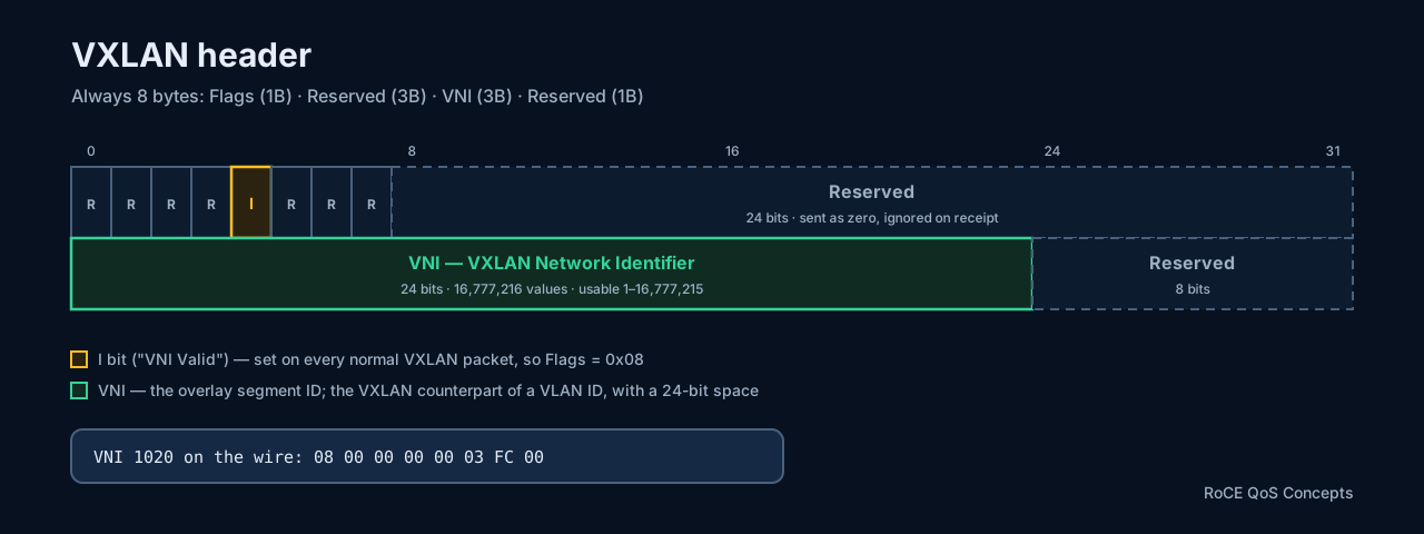
- Flags (1 byte). The only bit that matters is the I bit (“VNI Valid”), bit 3 of the byte:
00001000. Every normal VXLAN packet therefore carriesFlags = 0x08, meaning “the VNI field is valid and must be processed.” The remaining flag bits are reserved and set to zero. - Reserved (3 bytes). Sent as
0x000000, ignored on receipt. - VNI — VXLAN Network Identifier (3 bytes). 24 bits, so 2²⁴ = 16,777,216 values; the practical range is 1 to 16,777,215 with VNI 0 reserved.
- Reserved (1 byte). Also zero.
A worked example — a packet on VNI 1020 (1020 = 0x0003FC):
Flags       08          I flag set
Reserved    00 00 00
VNI         00 03 FC    VNI 1020
Reserved    00

Complete 8-byte header:  08 00 00 00 00 03 FC 00
VNI versus VLAN ID
The VNI plays the same role as a VLAN ID but with a vastly larger space, and a crucially different scope:
| Feature | VLAN | VXLAN |
|---|---|---|
| Identifier size | 12 bits | 24 bits |
| Approximate segments | 4,000 | 16 million |
| Scope | Local Layer 2 domain | Overlay across an IP network |
| Encapsulation | 802.1Q tag | UDP/IP encapsulation |
| Identifier | VLAN ID | VNI |
A switch locally maps VLAN → VNI (for example VLAN 20 → VNI 1020), and the VLAN number does not need to match on every VTEP — the VNI is what identifies the overlay segment:
Leaf1: VLAN 20  → VNI 1020   ┐
                              ├─ same VXLAN segment, because the VNI matches
Leaf2: VLAN 200 → VNI 1020   ┘
A complete encapsulated packet
Host A (192.168.20.10, MAC AA:AA:AA:AA:AA:AA) sends to host B (192.168.20.20, MAC BB:BB:BB:BB:BB:BB) across a fabric where Leaf1’s VTEP is 10.255.255.21 and Leaf2’s is 10.255.255.22, on VNI 1020:
Outer Ethernet
  Source MAC:       Leaf1 underlay MAC
  Destination MAC:  Next-hop router MAC

Outer IP
  Source IP:        10.255.255.21     (Leaf1 VTEP)
  Destination IP:   10.255.255.22     (Leaf2 VTEP)
  Protocol:         UDP

Outer UDP
  Source port:      Hash-derived from the inner flow
  Destination port: 4789

VXLAN
  Flags:            0x08
  VNI:              1020

Inner Ethernet
  Source MAC:       AA:AA:AA:AA:AA:AA
  Destination MAC:  BB:BB:BB:BB:BB:BB

Inner IP
  Source IP:        192.168.20.10
  Destination IP:   192.168.20.20
The underlay forwards on the outer IP addresses only; the tenant traffic rides untouched in the inner frame.
Why VXLAN uses UDP
The destination port (4789) identifies VXLAN; the source port is hashed from the inner flow’s five-tuple (inner source/destination IPs and ports plus protocol). Different inner flows therefore produce different outer source ports, and the underlay’s five-tuple ECMP hashing spreads them across paths:
Flow 1 → Spine1
Flow 2 → Spine2
Flow 3 → Spine3
This is the same entropy trick RoCEv2 plays with its own UDP source port (see the UDP header above) — encapsulations that hid everything inside one flow would collapse ECMP to a single path.
VXLAN overhead and MTU
IPv4, untagged:   14 (outer Eth) + 20 (outer IPv4) + 8 (UDP) + 8 (VXLAN) = 50 bytes
With outer 802.1Q:                                              50 + 4  = 54 bytes
Outer IPv6:       14 + 40 + 8 + 8                                       = 70 bytes
The overhead sits entirely outside the original inner frame. For a full-size 1500-byte inner IP packet:
Outer Ethernet           14
Outer IPv4               20
Outer UDP                 8
VXLAN                     8
Inner Ethernet           14
Inner IP packet        1500
---------------------------
Total before FCS       1564 bytes
So a 1500-byte underlay MTU cannot carry a full 1500-byte inner packet without fragmenting or dropping. Typical designs use 1550 minimum, 1600 for margin, or 9000/9216 in jumbo environments. It is the same class of problem as the RoCE MTU alignment checks in the RDMA tuning post — any hop whose MTU ignores the overhead silently breaks the path.
VTEP packet processing
At the ingress VTEP: receive the original frame → determine its local VLAN → map VLAN to VNI → determine the remote VTEP → add the VXLAN header → add outer UDP, IP, and Ethernet → forward through the underlay.
At the egress VTEP: receive the outer IP packet → recognize UDP destination 4789 → strip outer Ethernet/IP/UDP → read the VNI → map it to a local VLAN or bridge domain → strip the VXLAN header → forward the original inner frame.
The key idea is how little the VXLAN header itself carries — flags, VNI, reserved bits. Everything else comes from the other headers:
Outer headers = transport through the underlay (VTEP addresses, ECMP)
VXLAN VNI     = overlay segment identification
Inner headers = original tenant traffic
For how VXLAN segments are stitched together with EVPN control-plane learning, see the VXLAN EVPN architecture post.
The overall contrast worth remembering: TCP carries connection state, reliability, flow control, and congestion feedback in every header; RoCEv2 keeps the wire format minimal (UDP) and pushes all of that into RNIC hardware and the BTH layer.
Putting it together: a RoCEv2 packet through VXLAN EVPN, interactively
Everything this section stacked up — the RoCEv2 encapsulation from the top, the VXLAN wrapper, the VTEP processing — composes into a single packet’s journey, and the walkthrough below lets you follow one. It tracks one RC RDMA Write Only packet (1,024 B of data) from Host A’s RNIC through a VXLAN EVPN leaf-spine fabric into Host B’s registered memory: step through the five stages, toggle between same-subnet forwarding (L2 VNI) and inter-subnet symmetric IRB, and click any header block — outer Ethernet/IPv4/UDP/VXLAN, the inner tenant headers, BTH, RETH, iCRC, FCS — to inspect its fields and what happens to them at that hop. Watch the two integrity scopes it demonstrates: the iCRC that survives routing end to end because the mutable fields (TTL, IP checksum, DSCP/ECN) are normalized out of its calculation, and the link FCS that dies and is reborn on every wire.
Beyond the example payload: RDMA operation size versus RoCE path MTU
The DMA Data field in the walkthrough is the actual application payload — the bytes the verbs layer handed to the RNIC — but its 1,024 B is only an example size chosen to keep the hex readable. Real transfers are bigger, and the important distinction is that two different sizes live at two different layers:
- The RDMA operation size is whatever the application posts in one work request — 9 KB, 1 MB, or more.
- The RoCE data per packet is capped by the QP path MTU — usually 4,096 B at most.
Standard Linux/RoCE path-MTU choices are 256, 512, 1024, 2048, and 4096 bytes (see the ibv_modify_qp path-MTU values and the NVIDIA RDMA Aware Networks Programming User Manual). Setting the Ethernet interface MTU to 9000 therefore lets the RNIC step up to the full 4,096-byte path MTU — but not to a 9,000-byte RoCE payload per packet. Larger operations are simply segmented by the RNIC automatically, with no software in the loop. A 9,000-byte RDMA Write over a 4,096-byte path MTU becomes three packets:
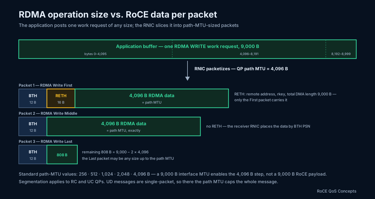
Only the First packet carries the RETH with the remote address, rkey, and total DMA length — the receiver’s RNIC places the Middle and Last packets from that starting address plus the BTH sequence numbers, the same state-in-hardware trade this section keeps returning to. (This segmentation applies to RC and UC QPs; UD messages are single-packet and therefore genuinely MTU-limited.)
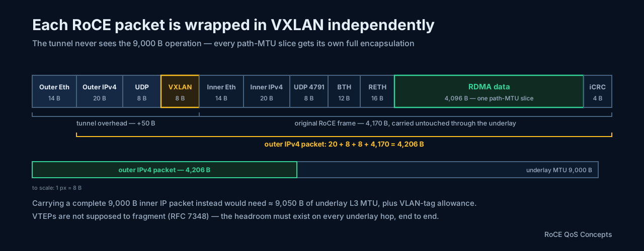
Each of those packets is then wrapped in VXLAN independently — the tunnel never sees the 9,000-byte operation, only its 4,096-byte slices:
The MTU budget works out comfortably for a jumbo underlay:
- A 4,096-byte RDMA data packet with RETH produces roughly a 4,206-byte outer IPv4 packet, so a 9,000-byte underlay MTU accommodates it easily.
- Transporting a complete 9,000-byte inner IP packet would instead need approximately 9,050 bytes of underlay L3 MTU, plus allowance for VLAN tags or other encapsulations.
- The headroom must exist end to end, because VXLAN VTEPs are not supposed to fragment (RFC 7348) — the same silent-breakage rule as the overhead arithmetic earlier in this section.
So the typical configuration layers up as:
Application RDMA operation:      any supported large size
RoCE QP path MTU:                4096 B         ← per-packet data ceiling
Ethernet / VXLAN underlay MTU:   9000 or 9216 B
In short: grow the RDMA operation size freely within device and application limits, and treat 4,096 B as the normal maximum RoCE data chunk per packet.
Packet-by-packet placement: the receiver has no reassembly buffer
What does the destination RNIC do with those three slices? It normally writes each valid, in-order RoCE packet directly into its final registered-memory location — it does not park the pieces in a separate reassembly buffer until all 9,000 bytes have arrived:
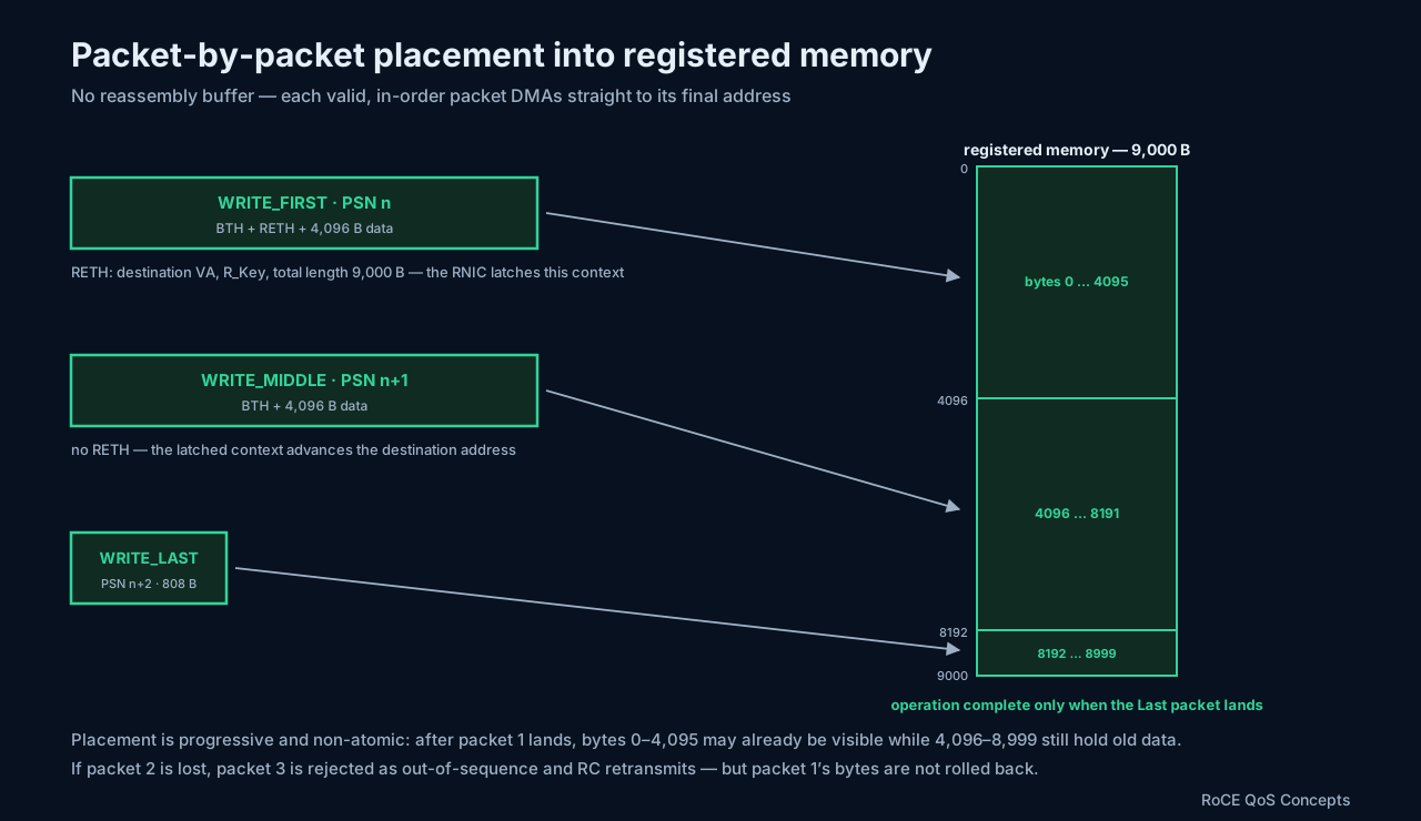
The First packet’s RETH carries the destination virtual address, R_Key, and total length; the RNIC latches that context and simply advances the destination address for the Middle and Last packets. Linux’s soft-RoCE responder shows this packet-by-packet placement directly in code (rxe_resp.c).
The consequences worth internalizing:
- This is RoCE transport segmentation, not IP fragmentation — nothing here involves the IP layer.
- The 9,000-byte write is not atomic. After packet 1, the first 4,096 bytes may already be visible while the remaining memory still contains old data.
- If packet 2 is lost, packet 3 is rejected as out-of-sequence. RC requests retransmission — but packet 1’s data is not rolled back.
- A plain RDMA Write generates no receiver-side CQE at all.
- RDMA Write With Immediate generates a receiver CQE only after the Last packet completes — which is exactly what lets the application know the complete buffer is ready.
So the receiver application should never consume the buffer merely because some bytes changed. It should wait for a Write With Immediate, an ordered SEND, or another application-level completion signal. The hardware may internally buffer or combine writes, but software must assume progressive, non-atomic placement.
CQE: the completion signal software actually waits for
A CQE — Completion Queue Entry — is the small status record the RNIC creates to tell software that a work request has completed. It is not a network packet and carries no application payload:
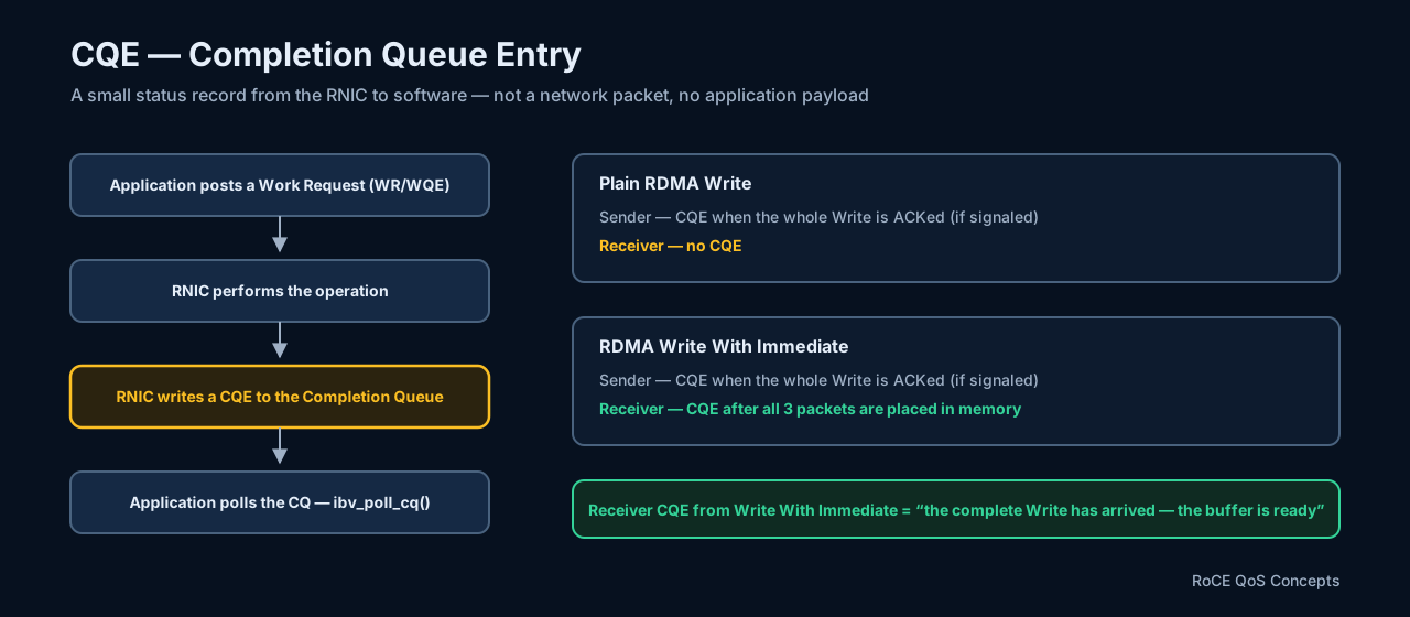
A CQE typically contains:
- success or error status
- the operation type, such as RDMA Write or Receive
- the application-provided
wr_id - the transferred byte count
- the QP number
- the immediate value, when applicable
For the three-packet write above, the two variants differ only at the receiver: a plain RDMA Write completes with a sender-side CQE (if the work request was signaled) once the whole write is acknowledged, and the receiver sees nothing; Write With Immediate adds a receiver CQE that fires only after all three packets have been placed into memory. That receiver CQE is effectively the signal “the complete RDMA Write has arrived; the destination buffer is now ready” — and the receiver application retrieves it with ibv_poll_cq().
ECN across the tunnel: how underlay congestion reaches the RNIC
The walkthrough above lists DSCP/ECN among the mutable fields normalized out of the iCRC — here is why that matters operationally. The entire DCQCN loop of section 10 depends on one thing: a CE mark reaching the destination RNIC. But once the packet is VXLAN-encapsulated, the RNIC’s copy of the IP header is buried inside the tunnel — a congested spine parses only as far as the outer header, so the outer header is the only place it can mark. Getting that mark back into the header the RNIC actually reads is a three-step relay, defined by the tunnel-ECN rules of RFC 6040 and extended to shim-header tunnels like VXLAN by RFC 9601:
- Encapsulation (ingress VTEP): copy the inner ECN field into the outer IPv4 header, so the packet enters the underlay as ECN-capable there too. The same copying applies to DSCP — the underlay’s queues, WRED/ECN thresholds, and PFC classification all act on the outer header, because it is the only header they see.
- Underlay congestion (a spine, or any transit hop): the congested queue marks the outer header CE. The inner header is untouched — no transit hop rewrites anything behind the VXLAN header.
- Decapsulation (egress VTEP): fold the mark back in — outer CE + inner ECT becomes inner CE. (The other decap rule worth knowing: outer CE + inner Not-ECT is dropped, not forwarded — a sender that never claimed ECN capability must not receive a signal it cannot interpret.)
The packet’s two ECN fields, state by state:
before congestion (ingress leaf → spine):   outer ECN = ECT  | VXLAN | inner ECN = ECT
at the congested spine:                     outer ECN = CE   | VXLAN | inner ECN = ECT
after egress-VTEP decapsulation:                    (no outer)          inner ECN = CE
From there the story rejoins section 10 as if the tunnel had never existed: the destination RNIC sees CE in the restored inner header and answers with a CNP (section 11) to the sender’s QP, and DCQCN reduces the sending rate. And when congestion hits a host-facing link — where the packet rides natively, as in steps 1 and 4 of the walkthrough — there is no tunnel and no relay: the inner RoCEv2 IPv4 header is marked directly.
So the rule set is:
- VXLAN underlay congestion → mark the outer IP ECN — the only header a transit hop owns
- Egress VTEP → propagate outer CE into the inner IP ECN at decapsulation
- Host-facing congestion → mark the inner IP ECN directly — it is the only IP header on the wire
The operational catch: the outer-to-inner CE propagation at decap is a capability, not a law of nature — it must be supported and enabled on the VTEPs. Cisco documents this behavior for Nexus VXLAN fabrics, and it follows RFC 6040/9601, but verify it per platform and per encapsulation before trusting DCQCN across a fabric. Without it, the underlay marks CE diligently and the egress VTEP throws the mark away with the rest of the outer header: the RNIC never learns about underlay congestion, no CNPs flow, DCQCN never engages, and the queues grow until PFC (if the underlay carries it end to end) or tail drops do the signaling instead — the exact escalation section 10’s PFC-versus-ECN comparison warns about, reproduced by one missing tunnel knob. The one thing this marking never breaks is the RoCE payload itself: ECN and DSCP rewrites at any hop are safe because both fields are normalized out of the iCRC calculation.
16. References
- Cisco Nexus 9000 Series NX-OS QoS Configuration Guide
- Cisco Nexus
random-detectcommand reference - SONiC configuration reference
- NVIDIA: Matching RoCEv2 BTH opcode and destination QP
- Broadcom: Introduction to Congestion Control for RoCE
ibv_modify_qp(3)man page — QP path-MTU values- NVIDIA RDMA Aware Networks Programming User Manual
ibv_poll_cq(3)man page — retrieving CQEs- Linux soft-RoCE responder source (
rxe_resp.c) — packet-by-packet placement - RFC 7348: Virtual eXtensible Local Area Network (VXLAN)
- RFC 6040: Tunnelling of Explicit Congestion Notification
- RFC 9601: Propagating Explicit Congestion Notification Across IP Tunnel Headers Separated by a Shim