
RoCE_Cumulus_Linux
Part 1: RoCE and RDMA fundamentals
In the context of NVIDIA/Cumulus Linux and HPC networking, RoCE stands for:
RoCE = RDMA over Converged Ethernet
It is widely used in AI clusters, HPC, GPU clusters, storage networks, and low-latency data centers.
What is RoCE?
RoCE allows RDMA (Remote Direct Memory Access) to run over an Ethernet network.
Normally, when one server sends data to another:
Application
     |
     v
TCP/IP Stack
     |
     v
Kernel
     |
     v
NIC
     |
     v
Ethernet
The CPU has to copy memory, handle interrupts, process TCP/IP, and switch between user and kernel space. This consumes CPU cycles and adds latency.
With RDMA, the path becomes:
Application
     |
     v
RNIC (RDMA NIC)
     |
     v
Ethernet
The NIC transfers data directly between the memory of two servers, bypassing most of the operating system.
Benefits include:
- Extremely low latency (NIC-added latency often under 2 microseconds; end-to-end latency across hops and under load is typically a few microseconds)
- High throughput (100G, 200G, 400G, and 800G)
- Very low CPU utilization
- Zero-copy data transfer
What is RDMA?
RDMA lets one computer directly access the memory of another computer without involving the remote CPU in the data path.
Traditional: CPU -> Kernel -> NIC
RDMA:        NIC -> Memory
The remote CPU does not have to process each network transfer.
Why use RoCE instead of InfiniBand?
InfiniBand already provides RDMA. RoCE brings RDMA capabilities to Ethernet networks.
| Feature | InfiniBand | RoCE |
|---|---|---|
| Transport | InfiniBand | Ethernet |
| RDMA | Yes | Yes |
| Ethernet compatible | No | Yes |
| Uses an existing Ethernet network | No | Yes |
| Cost | Often higher | Can be lower when Ethernet infrastructure already exists |
| Common in AI | Yes | Yes |
Many AI data centers choose RoCE because they can use high-speed Ethernet while still benefiting from RDMA.
There is also iWARP, an alternative that runs RDMA over TCP/IP. iWARP inherits TCP’s built-in reliability and routability, but it is generally harder to accelerate at the highest line rates. For modern data-center AI and HPC fabrics, RoCEv2 became the dominant Ethernet RDMA choice.
RoCE versions
RoCE comes in two versions. RoCEv1 runs directly over Layer 2 Ethernet (EtherType 0x8915) and cannot cross routers; RoCEv2 encapsulates RDMA in UDP/IP, making it routable across Layer 3 fabrics — which is why virtually all modern deployments use v2.
Side by side, the encapsulation difference is easy to see — v2 slips an IP/UDP envelope between Ethernet and the RDMA transport:
        RoCEv1                         RoCEv2
   (Layer 2 only)                (routable, Layer 3)

+---------------------+       +---------------------+
| Ethernet header     |       | Ethernet header     |
| EtherType 0x8915    |       +---------------------+
+---------------------+       | IP header           |
| InfiniBand transport|       | (DSCP + ECN fields) |
| + payload           |       +---------------------+
+---------------------+       | UDP header          |
| FCS                 |       | (dst port 4791)     |
+---------------------+       +---------------------+
                              | InfiniBand transport|
                              | + payload           |
                              +---------------------+
                              | FCS                 |
                              +---------------------+
Both stacks end with the FCS (Frame Check Sequence) — the 4-byte CRC-32 that closes every Ethernet frame. The sender’s NIC computes it over the frame contents and the receiver recomputes it to detect corruption: on a match the frame is accepted, on a mismatch it is silently discarded. FCS provides error detection only — no correction, no encryption — and it is stripped and regenerated at every Ethernet hop, so it is not an end-to-end check. End-to-end integrity for RoCE comes instead from the InfiniBand transport’s ICRC (invariant CRC), which travels unchanged from RNIC to RNIC.
That one difference sets the reach of each version:
RoCEv1:  Server ---- switch --X-- router ...            blocked at Layer 3;
                                                        one broadcast domain
RoCEv2:  Server -- leaf -- spine -- leaf -- Server      crosses routed fabrics
Packet formats and the version differences are covered in detail in the configuration guide below.
Why does RoCE need a lossless Ethernet network?
RDMA performance can degrade sharply when packets are dropped. Classic RoCE transports retransmit with go-back-N: after a single lost packet, the sender re-sends that packet and everything after it, so one drop can waste a large amount of already-delivered work. Loss therefore leads to lower throughput, higher latency, and slower GPU jobs. Ethernet is commonly configured to behave like an effectively lossless fabric for selected RoCE traffic. (Newer RNICs add selective-repeat and better out-of-order handling, which softens — but does not eliminate — RoCE’s sensitivity to loss.)
Cumulus Linux and RoCE
NVIDIA Cumulus Linux provides features used to build a reliable RoCE fabric:
- Priority Flow Control (PFC) pauses selected priorities rather than an entire link.
- Explicit Congestion Notification (ECN) signals congestion before buffers overflow.
- Data Center Bridging (DCB) supports traffic classes and priority treatment.
- QoS places RDMA traffic into the intended queues and schedules it appropriately.
GPU Server
   |
ConnectX NIC
   |
100/200/400G Ethernet
   |
Spectrum Switch (Cumulus Linux)
   |
100/200/400G Ethernet
   |
GPU Server
The ConnectX RNICs perform RDMA. Spectrum switches running Cumulus Linux forward, classify, queue, mark, and protect the traffic.
Typical AI cluster architecture
+-----------------------------+
| GPU Server                  |
| H100/H200/B200              |
| ConnectX-7/8 RNIC           |
+-------------+---------------+
              |
          400G Ethernet
              |
       +--------------+
       | Spectrum-4   |
       | Cumulus      |
       +--------------+
              |
          Spine Switch
              |
       +--------------+
       | Spectrum-4   |
       +--------------+
              |
         Another GPU Server
Thousands of GPUs can communicate through RoCE over this Ethernet fabric.
Key network design considerations
- Enable PFC only for the intended RDMA priority to reduce head-of-line blocking.
- Configure ECN so congestion is signaled before packet loss occurs.
- Use a consistent MTU, often jumbo frames, across the fabric.
- Keep the fabric symmetric and use equal-cost paths where appropriate.
- Ensure switch buffers are sized and profiled for the workload and platform.
- Tune RNIC queue pairs, completion queues, and related settings for the application.
RoCE vs. TCP/IP
| Feature | TCP/IP | RoCE |
|---|---|---|
| CPU usage | High | Very low |
| Memory copies | Multiple | Zero-copy |
| Latency | Often 20-100 microseconds | Often 1-5 microseconds |
| Throughput | Good | Near line rate |
| Recovery | TCP retransmission | RDMA transport and congestion mechanisms |
| GPU communication | Moderate | Excellent |
| AI/HPC suitability | General purpose | Highly suitable |
With the concepts covered, the rest of this post turns from theory to practice: configuring and operating RoCEv2 on NVIDIA Spectrum switches running Cumulus Linux.
Part 2: Configuring RoCEv2 on NVIDIA Spectrum switches with Cumulus Linux
A functioning RoCE network involves three layers:
Application
   |
   |  MPI / NCCL / NVMe-oF / storage application
   v
RDMA transport
   |
   |  ConnectX or BlueField RNIC
   v
Ethernet fabric
   |
   |  Spectrum switches running Cumulus Linux
   v
Remote RNIC and application memory
The switch does not perform RDMA. The RNICs perform RDMA. The switch’s job is to:
- Classify RoCE packets correctly.
- Place them into appropriate queues.
- Detect congestion.
- Mark packets with ECN.
- Use PFC selectively when necessary.
- Avoid packet drops and prolonged pause conditions.
Modern Cumulus Linux releases provide an NVUE RoCE profile that configures these mechanisms together. Exact commands and defaults can differ by hardware platform and software release.
1. The components of a RoCE network
Consider this small fabric of two directly connected leaf switches:
          Server-1
       ConnectX RNIC
        200G Ethernet
              |
            swp1
       +--------------+
       | Leaf-1       |
       | Spectrum     |
       | Cumulus      |
       +--------------+
            swp49
              |
         400G uplink
              |
            swp49
       +--------------+
       | Leaf-2       |
       | Spectrum     |
       | Cumulus      |
       +--------------+
            swp1
              |
        200G Ethernet
       ConnectX RNIC
          Server-2
Suppose Server-1 sends a large RDMA write to Server-2. The sequence is:
- Server-1’s RNIC constructs RoCEv2 packets.
- The packets contain IP and UDP headers.
- The switch classifies them according to DSCP or PCP.
- The switch maps the classification to an internal switch priority.
- That priority maps to a priority group and egress traffic class.
- When the destination link becomes congested, the switch marks eligible packets with ECN.
- The receiver returns a CNP (Congestion Notification Packet).
- The sender’s RNIC reduces its transmission rate.
- If buffering reaches a more critical level in a lossless configuration, PFC can temporarily pause the affected priority.
The desired behavior is:
Normal operation:
No congestion -> no ECN -> no PFC

Moderate congestion:
ECN marking -> sender slows down

Severe or sudden congestion:
PFC pause -> prevent loss while congestion control reacts
PFC should be viewed as a last line of protection, not the primary congestion-control mechanism.
2. RoCEv1 versus RoCEv2
RoCEv1
RoCEv1 is encapsulated directly in Ethernet:
Ethernet
`-- RoCE / InfiniBand transport
It is a Layer 2 protocol (EtherType 0x8915) and normally remains inside the same Ethernet broadcast domain.
RoCEv2
RoCEv2 adds IP and UDP:
Ethernet
`-- IP
    `-- UDP
        `-- RoCE transport
This allows RoCEv2 to cross routed Layer 3 fabrics.
A typical RoCEv2 packet looks conceptually like:
+---------------------------+
| Ethernet header           |
+---------------------------+
| IPv4 or IPv6 header       |
| DSCP and ECN fields       |
+---------------------------+
| UDP header                |
| Destination port 4791     |
+---------------------------+
| RDMA transport headers    |
+---------------------------+
| Application payload       |
+---------------------------+
| Frame check sequence      |
+---------------------------+
UDP destination port 4791 identifies RoCEv2 and stays fixed for every flow, while the RNIC varies the UDP source port per queue pair so that ECMP hashing can spread flows across paths (see the ECMP section below). Production switches usually classify trusted RoCE traffic using DSCP or PCP rather than relying only on the UDP port.
3. The QoS processing pipeline
The most important concept is the QoS mapping pipeline:
Packet marking
    |
    | DSCP or PCP
    v
Switch priority
    |
    v
Priority group / ingress buffer
    |
    v
Traffic class / egress queue
    |
    +-- ECN
    +-- scheduling
    `-- PFC association
These terms are related but not identical.
DSCP
DSCP is a six-bit field in the IP header.
IPv4/IPv6 packet
`-- DS field
    |-- DSCP: 6 bits
    `-- ECN:  2 bits
DSCP is useful in a routed RoCEv2 fabric because it survives Layer 3 forwarding.
DSCP 26 -> Switch priority 3 -> Traffic class 3
The exact DSCP value is a design choice and must match the RNIC, switch, and application configuration.
PCP
PCP is a three-bit priority field in an 802.1Q VLAN tag:
802.1Q VLAN tag
|-- PCP: 3 bits
|-- DEI: 1 bit
`-- VLAN ID: 12 bits
PCP provides priorities 0 through 7. It is common in Layer 2 environments, but it is less suitable as the only classification mechanism in a routed fabric because VLAN headers are rewritten or removed at Layer 3 boundaries.
Switch priority
The switch converts DSCP or PCP into an internal priority, typically 0-7.
Priority group
An ingress priority group determines how traffic uses ingress buffers. A lossless RoCE priority normally receives protected buffering and can be associated with PFC.
Traffic class
A traffic class generally represents an egress queue.
Switch priority 3 -> Traffic class 3 -> ECN-enabled egress queue
4. Priority Flow Control
PFC is defined by IEEE 802.1Qbb. Normal Ethernet pause affects the entire link; PFC can pause an individual priority.
PFC pause for priority 3
        |
        v
Stop priority 3 temporarily
        |
        |-- Priority 0 continues
        |-- Priority 1 continues
        `-- Priority 6 continues
A PFC frame contains a pause time for each of eight priorities.
Example
Assume Leaf-2 receives 400 Gb/s on its uplink port (swp49, facing Leaf-1) but can forward only 200 Gb/s toward Server-2:
400G ingress
     |
     v
+------------+
| Leaf-2     |
| Buffer     |------> 200G server port
+------------+
The queue grows at approximately:
400 Gb/s - 200 Gb/s = 200 Gb/s
The switch first marks packets using ECN. If the queue continues growing and reaches the PFC threshold, Leaf-2 sends a PFC pause frame upstream:
Leaf-2 ---- PFC pause priority 3 ----> Leaf-1
Leaf-1 temporarily stops sending priority-3 traffic on that link.
Why not enable PFC on every priority?
Because broad PFC deployment can produce:
- Head-of-line blocking
- Congestion spreading
- Pause storms
- Circular buffer dependencies
- Fabric-wide performance collapse
- Deadlock in badly designed topologies
A common design is:
Priority 3: RoCE data, PFC enabled
Priority 6: control traffic, no PFC
Priority 0: ordinary best-effort traffic, no PFC
Exact assignments must follow a validated design rather than being copied blindly.
5. ECN
ECN is a congestion-signaling mechanism carried in the IP header.
| Value | Meaning |
|---|---|
00 | Not ECN capable |
01 | ECN-capable transport |
10 | ECN-capable transport |
11 | Congestion experienced |
When a switch queue exceeds a configured threshold, the switch changes the ECN field to Congestion Experienced rather than dropping the packet.
Queue below threshold:
ECT packet -> forward unchanged

Queue above ECN threshold:
ECT packet -> mark CE -> forward
The receiver detects the congestion mark and returns a Congestion Notification Packet (CNP) — a dedicated RoCEv2 control packet — to the sender. The sender’s RNIC congestion-control algorithm then reduces its sending rate.
Sender RNIC                      Receiver RNIC
    |                                  |
    |---- RoCE packet ---------------->|
    |     switch marks CE              |
    |                                  |
    |<--- CNP (congestion signal) -----|
    |                                  |
    `---- reduce transmission rate
RoCE congestion control commonly uses DCQCN (Data Center Quantized Congestion Notification) or vendor-specific enhancements. DCQCN divides the work across three roles:
- Congestion Point – the switch, which ECN-marks packets (CE) once a queue crosses its threshold.
- Notification Point – the receiver, which sees the CE mark and sends a CNP back to the sender.
- Reaction Point – the sender, which cuts its injection rate on each CNP and gradually recovers when the marks stop.
The goal is to throttle senders early, using ECN and CNP, so flows rarely reach the PFC pause threshold — PFC stays a last-resort backstop. The exact algorithm depends on the RNIC, firmware, driver, and platform.
6. ECN and PFC thresholds
A simplified queue model looks like this:
Buffer occupancy
0 KB                                                     Full
 |                                                         |
 +---- normal ----+---- ECN marking -----+---- PFC --------+
                  |                      |
             ECN minimum            PFC XOFF
             threshold              threshold
The thresholds should be ordered so congestion control has time to work:
ECN threshold < PFC XOFF threshold < packet-drop threshold
This single axis is a simplification: on real switches the ECN (Kmin/Kmax) thresholds are measured against the egress traffic-class queue, while the PFC XOFF threshold and headroom are measured against the ingress priority-group buffer. The ordering expresses design intent — ECN should engage before PFC — rather than positions in one physical queue; it is also why Section 13 reads ingress-buffer and egress-queue counters separately.
A more complete model is:
Low occupancy
    |
    | No marking
    v
ECN minimum threshold
    |
    | Increasing or deterministic ECN marking
    v
ECN maximum threshold
    |
    | Heavy ECN marking
    v
PFC XOFF threshold
    |
    | Send pause frame upstream
    v
Maximum available buffer
    |
    | Packet drop if exhausted
In DCQCN terms the two ECN queue thresholds are called Kmin and Kmax, and the maximum marking probability is Pmax (frequently 100%): no marking below Kmin, a probability that rises from Kmin and reaches Pmax at Kmax, with every packet marked above Kmax. These marking parameters — not just the PFC XOFF point — are the primary congestion-tuning knobs, and a validated platform profile normally sets them for you.
Why headroom is necessary
After a switch transmits a PFC frame, traffic does not stop immediately. Packets already exist in the upstream transmitter, on the cable, and in switch pipelines. The switch therefore needs enough ingress headroom for traffic that arrives after PFC XOFF is triggered.
H >= R x T + B
Where:
- H = required headroom
- R = link rate
- T = total pause reaction time
- B = additional implementation and packet-size allowance
At 400 Gb/s, every microsecond represents approximately:
400 x 10^9 bits/s x 1 microsecond = 400,000 bits = 50,000 bytes
Even a few microseconds of reaction time can consume hundreds of kilobytes of buffer. Manually inventing thresholds is risky; use a validated platform-specific RoCE profile unless detailed buffer modeling has been performed.
7. Lossless versus lossy RoCE
Lossless RoCE
Uses ECN + PFC.
Advantages:
- Protects against transient packet loss.
- Fits established RoCE deployment models.
- Can suit sensitive storage and AI traffic when properly engineered.
Disadvantages:
- More configuration complexity.
- PFC can spread congestion.
- Requires consistent configuration on every hop.
- Requires watchdog and monitoring.
- Misconfiguration can create serious performance problems.
Lossy RoCE
Uses ECN without PFC.
Advantages:
- No pause propagation.
- Reduced risk of PFC deadlock.
- Operationally simpler in some designs.
- Better failure isolation.
Disadvantages:
- The RNIC and congestion-control implementation must tolerate occasional loss.
- Requires careful tuning and modern endpoint behavior.
- Not all workloads or reference architectures support it equally.
8. Basic Cumulus Linux RoCE configuration
For a current NVUE-based Cumulus Linux release, the high-level lossless configuration is:
sudo nv set qos roce
sudo nv config apply
To configure lossy RoCE:
sudo nv set qos roce mode lossy
sudo nv config apply
Note that nv set qos roce alone selects the default lossless profile, but on a switch already in lossy mode it does not revert the mode by itself — set it explicitly with nv set qos roce mode lossless.
A safer workflow stages and inspects the change before applying it:
sudo nv set qos roce
sudo nv config diff
sudo nv config apply
Then inspect operational state:
nv show qos roce
nv show interface swp1 qos roce counters
nv show interface swp1 qos roce status
Available display paths can vary slightly by Cumulus Linux version.
This one-liner is deliberately treated as a black box here — Part 3 at the end of this post opens it up: what the command actually programs, which defaults are safe, and the buffer-split lore that deserves a fact-check.
9. Example small laboratory deployment
Topology
Server-A                     Server-B
192.168.100.11               192.168.100.12
ConnectX-6 Dx                ConnectX-6 Dx
     |                            |
   swp1                         swp2
     `-------- Spectrum switch ---'
              Cumulus Linux
Assumptions:
- RoCEv2
- One VLAN or routed subnet
- MTU 9216 in the switch fabric
- Host MTU 9000
- Both hosts use the same traffic-class policy
- RoCE is configured as lossless
Step 1: Configure switch interfaces
This lab uses the Layer 2 same-subnet design (both hosts share 192.168.100.0/24, matching the topology above), so both ports join one bridge:
sudo nv set interface swp1,swp2 bridge domain br_default
sudo nv set interface swp1,swp2 link mtu 9216

sudo nv config apply
A routed design would instead put each host in its own subnet (for example swp1 192.168.101.1/24 with Server-A at 192.168.101.11/24, and swp2 192.168.102.1/24 with Server-B at 192.168.102.11/24, each host using its switch port as gateway) — Section 10’s addresses and ping targets would change to match. The key requirement is consistent MTU and QoS treatment end to end.
Verify that the bridge membership and MTU were applied:
nv show interface swp1
nv show interface swp2
Step 2: Enable the Cumulus RoCE profile
sudo nv set qos roce
sudo nv config diff
sudo nv config apply
Step 3: Verify the switch configuration
nv show qos roce
nv show interface swp1 qos roce status
nv show interface swp2 qos roce status
Verify PFC state, ECN-enabled traffic classes, classification mapping, the lossless priority, buffer-pool mapping, and traffic-class mapping.
10. Host configuration example
The hosts need an RDMA-capable NIC, suitable firmware, RDMA drivers, and RDMA user-space tools.
lspci | grep -i ethernet
ibv_devices
ibv_devinfo
rdma link show
A ConnectX device may appear as mlx5_0.
Configure host IP addresses
Server-A:
sudo ip address add 192.168.100.11/24 dev ens6f0np0
sudo ip link set ens6f0np0 mtu 9000
sudo ip link set ens6f0np0 up
Server-B:
sudo ip address add 192.168.100.12/24 dev ens6f0np0
sudo ip link set ens6f0np0 mtu 9000
sudo ip link set ens6f0np0 up
Check connectivity and MTU:
ping 192.168.100.12
ping -M do -s 8972 192.168.100.12
For IPv4, 8972 bytes commonly tests a 9000-byte IP MTU:
8972 payload + 20-byte IPv4 header + 8-byte ICMP header = 9000 bytes
Exact usable sizes differ when encapsulation is present.
11. Configure traffic marking on the hosts
RNIC-generated traffic must receive the DSCP or PCP value expected by the switches.
Host DSCP
    |
    v
Switch DSCP mapping
    |
    v
Switch priority
    |
    v
Traffic class
    |
    v
PFC and ECN policy
Example policy:
RoCE data:
DSCP 26 -> switch priority 3 -> traffic class 3

Congestion notification:
DSCP 48 -> switch priority 6 -> traffic class 6
These values are only examples. Check the RNIC and reference architecture.
Host-side commands (ConnectX / MLNX_OFED)
For a ConnectX host implementing the example policy (RoCE data DSCP 26 → priority 3, lossless):
# Trust DSCP (not PCP) for priority classification on the NIC
sudo mlnx_qos -i ens6f0np0 --trust dscp

# Map DSCP 26 to priority 3 on the host NIC (must match the switch policy)
sudo mlnx_qos -i ens6f0np0 --dscp2prio set,26,3

# Enable PFC on priority 3 only (must match the switch)
sudo mlnx_qos -i ens6f0np0 --pfc 0,0,0,1,0,0,0,0

# Mark RDMA-CM connections with ToS 106
# (ToS = DSCP x 4 + ECN bits: 26 x 4 = 104, plus ECT(0) = 106)
sudo cma_roce_tos -d mlx5_0 -t 106

# Default RDMA-CM connections to RoCEv2 on port 1 (mode 2 = RoCEv2)
sudo cma_roce_mode -d mlx5_0 -p 1 -m 2

# Device-wide default ToS for all QPs on the port. This is a fallback:
# applications that set their own ToS override it.
echo 106 | sudo tee /sys/class/infiniband/mlx5_0/tc/1/traffic_class
Applications can also mark for themselves:
# perftest: use -T/--tos together with -R (RDMA-CM connected QPs).
# Careful: lowercase -t is tx-depth, not ToS.
ib_write_bw -d mlx5_0 -R -T 106 192.168.100.12 --report_gbits

# NCCL: set the traffic class for NCCL's QPs
export NCCL_IB_TC=106
Verify the host NIC state — trust mode, the DSCP-to-priority table, and per-priority PFC — with the bare command:
mlnx_qos -i ens6f0np0
CNPs sent by the notification point default to DSCP 48, priority 6 on ConnectX. If the fabric uses different values, they are tunable via /sys/class/net/<iface>/ecn/roce_np/cnp_dscp and .../cnp_802p_prio.
On the switch side, confirm the same mappings:
nv show interface swp1 qos mapping dscp
nv show interface swp1 qos mapping pcp
nv show interface swp1 qos egress-queue-mapping
nv show interface swp1 qos remark
Other host tools such as tc and dcb/lldptool can also participate. The commands above assume MLNX_OFED / DOCA-Host tooling; availability and exact syntax depend on the host software stack.
12. Testing RoCE with perftest
The perftest package contains common RDMA tools:
ib_write_bw
ib_read_bw
ib_send_bw
ib_write_lat
ib_read_lat
ib_send_lat
Bandwidth test
On Server-B:
ib_write_bw -d mlx5_0 --report_gbits
On Server-A:
ib_write_bw -d mlx5_0 192.168.100.12 --report_gbits
For RoCEv2, select the correct GID index if required:
ib_write_bw -d mlx5_0 -x <gid-index> 192.168.100.12 --report_gbits
Inspect GIDs with:
show_gids
ibv_devinfo -v
Latency test
On Server-B:
ib_write_lat -d mlx5_0
On Server-A:
ib_write_lat -d mlx5_0 192.168.100.12
Bidirectional test
On Server-B:
ib_write_bw -d mlx5_0 --bidirectional --report_gbits
On Server-A:
ib_write_bw -d mlx5_0 --bidirectional 192.168.100.12 --report_gbits
Note: perftest marks -b/--bidirectional as a symmetric option — it must be given on both server and client. If only one side uses it, the test hangs or reports misleading results rather than failing cleanly, which can look like a fabric problem.
Expected throughput depends on link rate, PCIe generation and width, CPU/NUMA placement, message size, queue count, firmware, congestion control, encryption, and virtualization. A 200 Gb/s link will not report exactly 200 Gb/s of application payload because protocol headers consume line rate.
13. Monitoring the switch
Most QoS counters come from a single command, whose output is split into PFC Statistics, Ingress Buffer Statistics, and Egress Queue Statistics sections:
nv show interface swp1 counters qos
RoCE-specific byte/packet and ECN/CNP counts come from nv show interface swp1 qos roce counters.
PFC statistics
The PFC Statistics section of nv show interface swp1 counters qos reports pause frames per switch-priority. Conceptual output:
switch-priority  rx-pause-frames  tx-pause-frames
---------------  ---------------  ---------------
0                0                0
1                0                0
2                0                0
3                120              45
4                0                0
5                0                0
6                0                0
7                0                0
tx-pause-frames: the switch asked its upstream neighbor to pause.rx-pause-frames: a neighbor asked this switch to pause.- Some PFC during controlled bursts can be normal.
- Continuously increasing counters indicate persistent congestion or incorrect threshold/rate design.
ECN marking
RoCE ECN/CNP counts come from nv show interface swp1 qos roce counters. Conceptual output:
tx-ecn-stats
  ecn-marked-packets         152430
tx-cnp-stats
  cnp-packets                3210
rx-pfc-stats
  pause-packets              0
tx-pfc-stats
  pause-packets              22
tx-roce-stats
  unicast-no-buffer-discard  0
Healthy behavior under load is generally:
ECN marks: some
PFC frames: low or occasional
Buffer discards: zero
Zero ECN with very high PFC can indicate ECN thresholds that are too high, incorrect classification, or ineffective endpoint congestion control.
Ingress buffer discards
The Ingress Buffer Statistics section of nv show interface swp1 counters qos shows ingress-buffer drops. Any discard on the RoCE priority deserves investigation.
Egress queue state
The Egress Queue Statistics section of nv show interface swp1 counters qos, together with the scheduler and congestion-control config, shows egress behavior:
nv show interface swp1 qos congestion-control
nv show interface swp1 qos egress-scheduler
These help identify which queue is congested, whether ECN is enabled, whether traffic is mapped correctly, whether scheduling causes starvation, and whether packets are dropped.
At scale, single snapshots matter less than trends: export the PFC-pause, ECN-mark, and CNP counters to your telemetry system and watch their rate over time — a slow, steady climb is the early warning a one-off nv show will miss.
14. PFC watchdog
A PFC pause storm can leave a traffic class paused for an excessive period.
Server with faulty NIC
       |
       | continuous PFC pause
       v
Leaf switch
       |
       | pause propagates
       v
Spine and other leaves
PFC watchdog detects long-running pause conditions and can take action to break them.
nv show interface swp1 qos pfc-watchdog
nv show interface swp1 qos pfc-watchdog status
Watchdog action must match application requirements. Breaking a pause storm may deliberately allow packet loss, which is usually preferable to fabric-wide deadlock.
15. Multi-hop leaf-spine example
 GPU-1       GPU-2                      GPU-3       GPU-4
   |           |                          |           |
   `----- Leaf-1 -----+              +---- Leaf-2 ----'
                      |              |
                      +---- Spine ---+
Every port along the RoCE path must agree on:
- MTU
- DSCP/PCP classification
- Switch-priority mapping
- Traffic-class mapping
- ECN behavior
- PFC priority
- Buffer policy
A single mismatched port can break lossless behavior.
Server marks DSCP 26
        |
Leaf-1 maps DSCP 26 -> priority 3
        |
Spine maps DSCP 26 -> priority 0
        |
Leaf-2 maps DSCP 26 -> priority 3
At the spine, traffic enters a best-effort queue. The result can be packet loss, missing ECN, no applicable PFC protection, unexpected latency, and low NCCL or RDMA throughput.
16. ECMP and packet ordering
RoCEv2 commonly runs over Layer 3 leaf-spine fabrics using ECMP.
Leaf-1
  |-- Spine-1 --+
  |-- Spine-2 --+-- Leaf-2
  `-- Spine-3 --+
Traditional ECMP commonly hashes source IP, destination IP, IP protocol, source UDP port, and destination UDP port. All packets in one hash flow should normally follow the same path to preserve order.
For RoCEv2 the only real entropy in that tuple is the UDP source port, which the RNIC varies per queue pair (the destination port is always 4791 and the IP pair is fixed for a given server pair). When a job’s traffic collapses into a few queue pairs, ECMP sees only a few flows and cannot spread them — which is exactly how the collisions below arise.
AI workloads can create a small number of very large flows:
Flow A -> Spine-1 at 100%
Flow B -> Spine-1 at 100%
Flow C -> Spine-2 at 20%
Flow D -> Spine-3 at 10%
Even when total fabric capacity is available, hash collisions can congest one path. Possible improvements include:
- More ECMP paths
- Better RNIC entropy (more source-port variation)
- QP-aware or UDF-based hashing that keys on RoCE fields
- Packet spraying — per-packet load balancing, with the RNIC reassembling out-of-order arrivals
- Adaptive/flowlet routing
- Congestion-aware mechanisms
- Rail-optimized GPU topologies
These require compatible switches, NICs, firmware, and a validated architecture.
17. Common failure scenarios
Scenario 1: Low throughput but no packet drops
Possible causes include incorrect NUMA placement, small RDMA messages, the wrong GID index, a PCIe bottleneck, ECN over-marking, aggressive RNIC rate reduction, an unintended queue, or a link at the wrong speed.
ibv_devinfo
rdma link show
ethtool ens6f0np0
numactl --hardware
nv show interface swp1
nv show interface swp1 qos roce status
Scenario 2: High PFC counters
Possible causes include oversubscription, a slow receiver, link-speed mismatch, ECN thresholds that are too high, ineffective endpoint congestion control, incorrect traffic classification, or incast.
Server-1 --+
Server-2 --+
Server-3 --+--> one destination server
Server-4 --+
nv show interface swp1 counters qos
nv show interface swp1 qos roce counters
Scenario 3: Packet drops despite PFC
Possible causes include PFC on the wrong priority, incorrect DSCP marking, DSCP rewriting, incomplete hop-by-hop configuration, insufficient headroom, excessive pause reaction time, physical-layer errors, or PFC disabled on the RNIC.
nv show interface swp1 qos mapping dscp
nv show interface swp1 qos egress-queue-mapping
nv show interface swp1 qos pfc
nv show interface swp1 qos roce status
Scenario 4: Entire fabric becomes slow
Possible causes include a PFC storm, deadlock, a faulty host continually sending pauses, PFC enabled on too many priorities, control traffic sharing the paused priority, or congestion spreading across hops.
nv show interface swp1 qos pfc-watchdog status
nv show interface swp1 counters qos
Identify where pause frames originate instead of assuming the most congested port is the root cause.
Scenario 5: Ping works, RDMA does not
Possible causes include a missing RDMA driver, wrong GID index, firewall blocking UDP 4791, RoCE mode disabled, address bound to the wrong RNIC, VLAN/MTU mismatch, incompatible driver/firmware, or an RDMA connection-manager problem.
ibv_devices
ibv_devinfo
show_gids
rdma link show
ping -M do -s 8972 <peer>
18. MTU design
A typical design uses jumbo frames:
Host IP MTU:       9000
Switch port MTU:   9216 or platform equivalent
Every hop must support the full frame:
Host MTU 9000
    |
Leaf MTU 9216
    |
Spine MTU 9216
    |
Leaf MTU 9216
    |
Host MTU 9000
A single lower-MTU hop can cause fragmentation for ordinary traffic, drops when Don’t Fragment is set, RDMA connection failures, or unexplained performance degradation. Jumbo frames improve efficiency but do not solve congestion by themselves.
19. Scheduling and bandwidth
RoCE commonly shares the switch with other traffic:
Traffic class 0: best effort
Traffic class 3: RoCE data
Traffic class 6: control or CNP (congestion-notification) traffic
Strict priority
The switch serves a high-priority queue until it is empty, then lower priorities. This reduces latency for the high-priority queue but can starve lower-priority traffic.
DWRR
Deficit Weighted Round Robin gives queues weighted shares.
TC0: weight 20
TC3: weight 70
TC6: weight 10
Weights guide scheduling when multiple queues are backlogged; they do not guarantee exact percentages at every instant.
nv show interface swp1 qos egress-scheduler
Control and congestion-notification traffic should not be trapped behind the congested data queue, or the feedback needed to stop congestion may itself be delayed.
20. A practical validation checklist
Physical layer
- Correct link speeds
- No symbol or FEC errors
- Correct optics and cables
- No unexpected lane degradation
Layer 2 / Layer 3
- Correct VLANs or routed subnets
- End-to-end IP reachability
- Consistent jumbo MTU
- Correct ECMP routes
- No unexpected asymmetric policy
QoS
- Hosts mark RoCE packets correctly
- DSCP/PCP maps to the expected switch priority
- Switch priority maps to the expected traffic class
- ECN is enabled on the RoCE queue
- PFC is enabled only on the intended lossless priority
- Headroom and buffer profile are platform validated
- Congestion-notification traffic is protected
Endpoint
- Correct NIC firmware
- Compatible driver
- Correct RoCE mode
- Correct GID index
- Congestion control enabled
- NUMA affinity aligned
- PCIe link width and speed correct
Operational behavior
- Zero buffer discards under expected load
- ECN marking appears during congestion
- PFC remains occasional rather than continuous
- No PFC watchdog events
- Expected RDMA bandwidth and latency achieved
21. Recommended troubleshooting sequence
Use a layered approach:
1. Physical link
       |
2. IP connectivity and MTU
       |
3. RDMA device and GID
       |
4. Packet classification
       |
5. ECN operation
       |
6. PFC operation
       |
7. Buffer and queue behavior
       |
8. Application performance
Useful switch commands include:
# Interface state
nv show interface swp1

# Complete RoCE summary
nv show interface swp1 qos roce status
nv show interface swp1 qos roce counters

# Classification
nv show interface swp1 qos mapping dscp
nv show interface swp1 qos mapping pcp

# Queue mapping
nv show interface swp1 qos egress-queue-mapping

# ECN configuration
nv show interface swp1 qos congestion-control

# PFC configuration
nv show interface swp1 qos pfc

# QoS counters (PFC, ingress-buffer, and egress-queue sections)
nv show interface swp1 counters qos

# RoCE ECN / CNP counters
nv show interface swp1 qos roce counters

# Scheduler
nv show interface swp1 qos egress-scheduler

# PFC watchdog
nv show interface swp1 qos pfc-watchdog status
Command paths can change between Cumulus Linux releases; confirm the syntax for the deployed release.
22. Security considerations
RoCE was designed for performance inside a trusted fabric, so security is largely bolted on rather than built in:
- Little native encryption or authentication. RoCEv2 packets are ordinary UDP/IP on the wire; a classic deployment offers no confidentiality or strong peer authentication. Options that add it at line rate include PSP (Google’s transport-security protocol) and IPsec offload on capable RNICs — both cost some performance and require support on the endpoints.
- RDMA exposes memory semantics. Because RDMA lets a peer read and write registered memory directly, spoofed or injected packets are more dangerous than with an ordinary socket. Keep RoCE on a trusted, isolated fabric (dedicated VLAN/VRF) and trust only the expected DSCP/PCP on ingress so untrusted traffic never reaches the lossless queues.
- Multi-tenancy / SR-IOV isolation. When one NIC is shared across tenants or VMs through SR-IOV, each virtual function must be isolated — QoS/rate limits, separate queue pairs, and per-VF policy — so one tenant cannot starve the lossless class, forge CNPs, or trigger PFC that harms others.
Treat RoCE security as a fabric-design property (isolation plus trusted classification), augmented by encryption offload where the workload requires it.
23. The central RoCE design principle
A healthy RoCE fabric should not simply be “lossless.” It should be congestion-controlled first and loss-protected second.
Good design:

Correct load balancing
        |
Early ECN marking
        |
RNIC rate adjustment
        |
PFC only for short transients
        |
No packet drops
A poor design relies constantly on PFC:
Persistent congestion
        |
Constant PFC
        |
Pause propagation
        |
Head-of-line blocking
        |
Fabric-wide performance degradation
The operational goal is not: “See many PFC frames, so lossless Ethernet is working.”
The healthier goal is: “ECN controls congestion, PFC is rare, and buffer discards remain zero.”
Topics beyond the scope of this post — worth exploring for AI-cluster fabrics — include rail-optimized topologies, ECMP entropy and adaptive routing, incast and oversubscription, NVIDIA Spectrum-X, the emerging Ultra Ethernet Consortium (UEC) transport designed to address RoCE’s limitations for AI/HPC, NCCL traffic patterns, and multi-NIC GPU server placement.
Part 3: Appendix — inside nv set qos roce, and the defaults worth checking
On most NOSes the equivalent lossless setup spans several layers of QoS configuration — Cumulus Linux compresses the whole thing into one command. Sections 8 and 9 used nv set qos roce exactly that way: as a black box. This appendix opens the box: what the command actually programs, the defaults that deserve scrutiny before production traffic arrives, and one piece of widely circulated buffer-pool lore that NVIDIA’s own documentation contradicts. The notes below come from lab work on Spectrum switches running Cumulus Linux 5.x; as everywhere in this post, verify the details against your release and platform.
The demo fabric for this appendix — and the first rule of the one-liner:
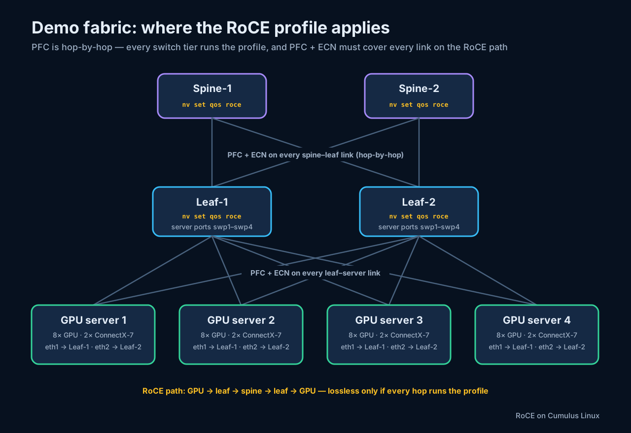
The profile goes on every switch tier, not just the leaves. PFC is a hop-by-hop mechanism (Section 4): a pause frame only protects the single link it is sent on. If the leaves run the RoCE profile but the spines do not, the spine–leaf hops have no lossless guarantee and the fabric silently degrades to Section 15’s mismatched-hop failure mode. Run nv set qos roce + nv config apply on the spines too — they generally do not need separately tuned ECN thresholds, but they do need the profile.
A.1 What the one command actually programs
On a switch with no RoCE mode set, nv set qos roce is equivalent to nv set qos roce mode lossless (recall Section 8’s caveat: it does not flip a switch already in lossy mode). Behind it, four things are configured at once:
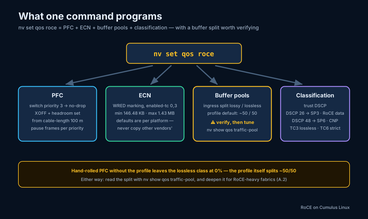
- PFC — switch priority 3 becomes no-drop, with XOFF and headroom values derived from the profile’s
cable-length(default 100 m — worth correcting if your cables are much longer, since headroom scales with round-trip time on the wire, Section 6). - ECN — WRED/ECN marking is enabled on TC3 and, per the profile default, on best-effort TC0 as well (
enabled-tc 0,3), with platform-derived min/max thresholds. - Buffer pools — ingress buffer is split between lossy and lossless pools. The profile itself sets a roughly even split; the widely repeated “lossless gets nothing” claim belongs to a different configuration entirely (A.2).
- Classification — the port trust mode and DSCP mapping follow the same policy used throughout this post: DSCP 26 → switch priority 3 (RoCE data, lossless TC3), DSCP 48 → switch priority 6 (CNP — which the profile schedules strict, unlike Section 19’s generic DWRR illustration).
Verify what the profile applied — the output shows the operational and applied columns side by side:
nv show qos roce
                    operational  applied
mode                lossless     lossless
cable-length        100          100
congestion-control
  min-threshold     146.48 KB    146.48 KB
  max-threshold     1.43 MB      1.43 MB
  enabled-tc        0,3          0,3
pfc
  pfc-priority      3            3
If operational and applied disagree, the commit did not fully take — re-run nv config apply before debugging anything else.
A.2 The buffer split: check the lore against the switch
A claim circulates widely in RoCE write-ups: “enabling the Cumulus RoCE profile leaves the lossless pool at 0% — PFC fires the moment traffic starts.” Checked against NVIDIA’s documentation, that claim is wrong for the profile — but it is true for a configuration that looks deceptively similar. The distinction matters enough to pin down precisely:
- With
nv set qos roce(lossless): the profile allocates the buffer split itself. Current NVIDIA docs show the lossless profile dividing ingress buffer roughly evenly —lossy-default-ingress Dynamic 50%,roce-reserved-ingress Dynamic 50%in the profile’s ownnv show qos rocebuffer output. The default is a sane starting point, not an empty pool. - With hand-rolled PFC and no RoCE profile (
nv set qos pfc ...built by hand): Cumulus’s base QoS default applies — 100% of memory indefault-lossy, nothing in a lossless pool — and that is where the “PFC fires immediately” behavior genuinely comes from. The lore appears to have transplanted this base-config fact onto the one-liner.
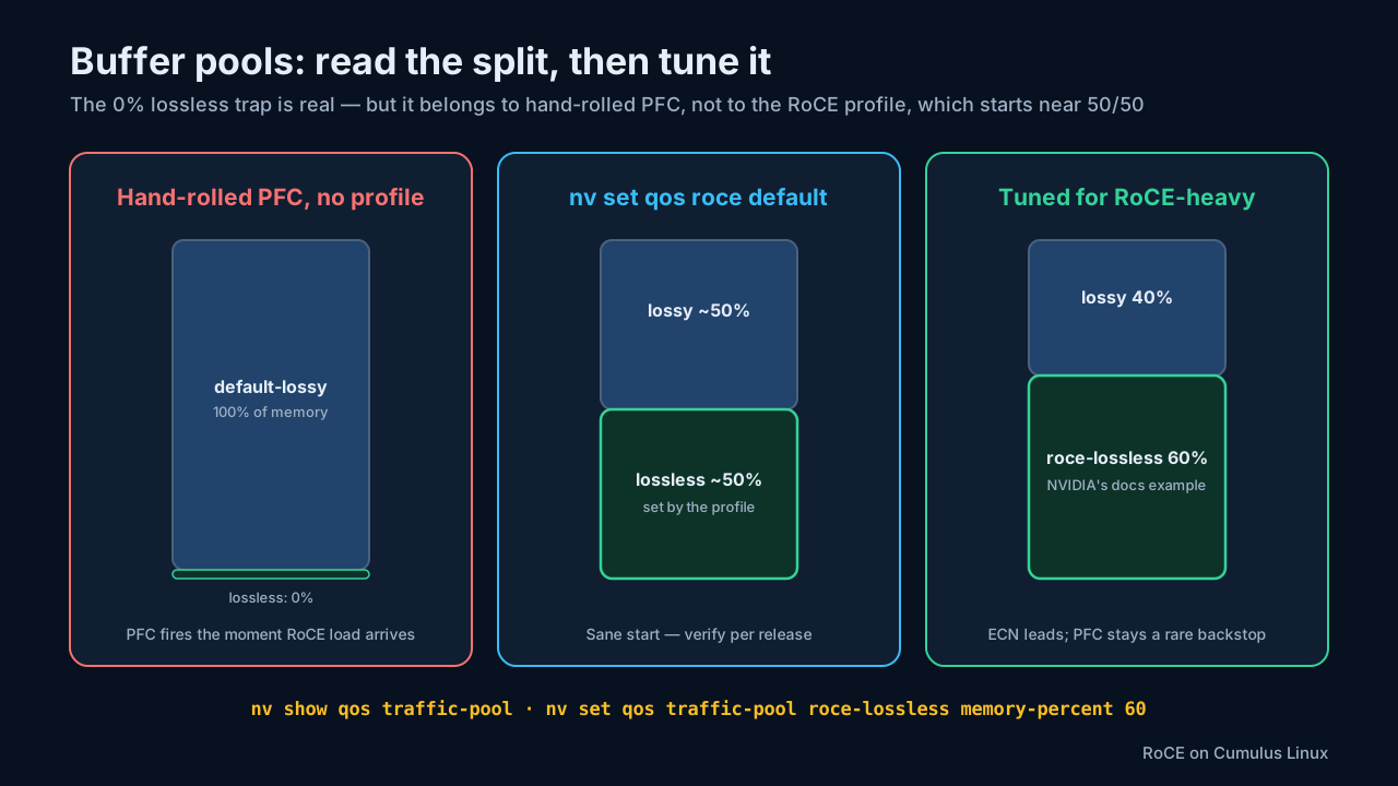
The operational rule that survives the fact-check: never assume the split — read it.
nv show qos traffic-pool
Then tune it to the traffic mix. Fabrics where RoCE dominates commonly deepen the lossless pool — NVIDIA’s own documentation example moves it to 60/40:
sudo nv set qos traffic-pool roce-lossless memory-percent 60
sudo nv set qos traffic-pool default-lossy memory-percent 40
sudo nv config apply
pool            memory-percent
roce-lossless   60
default-lossy   40
(Pool names can differ by release — list what your switch actually created with nv show qos traffic-pool before setting percentages.) A too-shallow lossless pool produces exactly Section 6’s failure: queues cross the PFC XOFF point early, and pause frames become the first line of defense instead of the last.
Cumulus 5.x also offers a mode that merges the lossy and lossless ingress pools into one, absorbing lossless bursts better than two rigid partitions:
sudo nv set qos roce mode lossless-single-ipool
sudo nv config apply
If several no-drop priorities interact badly on your platform, this single-ingress-pool mode is the first thing to try.
A.3 ECN thresholds: the configured value is not the hardware value
Cumulus has one behavior here that other platforms do not: the threshold you configure and the threshold the hardware programs are not identical. The default min-threshold displays as 146.48 KB in nv show qos roce, but the interface-level congestion-control view reports 156 KB (159,744 bytes) actually in force. NVIDIA documents the mismatch as expected ASIC threshold-programming behavior (called out for Spectrum-4 in current docs) — consistent with Spectrum’s cell-granular buffer accounting, and not a defect.
Two practical consequences:
- Never copy ECN thresholds from another vendor’s platform. The units differ (Cumulus takes bytes — a Cisco
30000pasted here means 30 KB, not 30 cells), the cell rounding differs, and the defaults were derived for different buffer architectures. Start from the Cumulus platform defaults and tune from evidence. - When you do tune, expect the operational value to differ slightly from what you typed.
Adjusting the thresholds (values in bytes, on the lossless traffic class):
sudo nv set qos congestion-control default-global traffic-class 3 min-threshold 150000
sudo nv set qos congestion-control default-global traffic-class 3 max-threshold 1500000
sudo nv config apply
nv show qos congestion-control default-global
traffic-class  min-threshold  max-threshold  probability
3              150000         1500000        100%
Evidence-driven tuning rules that have served well:
- PFC
tx-pausecounters climbing → ECN is marking too late; lowermin-thresholdby 20–30%. - ECN marking rate above ~5% of RoCE packets → marking too aggressively (throughput jitters as DCQCN over-throttles); raise
min-thresholdby 10–15%. - Keep at least ~40% of the shared lossless pool as budget between the ECN marking band and the PFC XOFF point, so DCQCN has room to act before PFC must — a pool-level budget expressing Section 6’s ordering, not positions in one physical queue (Section 6’s egress-vs-ingress caveat applies).
A.4 Configured state vs hardware truth
Section 13 covered the nv show counter set. The operational habit this appendix adds: nv show tells you what was configured and what the switch believes; ethtool reads the hardware counters directly. When the two disagree, believe ethtool.
| Question | Command |
|---|---|
| RoCE profile state (operational vs applied) | nv show qos roce |
| Per-port RoCE view | nv show interface swp1 qos roce status |
| Per-port RoCE/ECN/CNP counters | nv show interface swp1 qos roce counters |
| ECN thresholds in force | nv show qos congestion-control default-global |
| Buffer pool split | nv show qos traffic-pool |
| PFC pause counters, hardware-level | ethtool -S swp1 | grep -i pause |
| ECN marks, hardware-level | ethtool -S swp1 | grep ecn |
The two-command health check (counter names vary slightly by driver release — the Spectrum driver exposes per-priority pause counters, which is what you want, since PFC is per-priority):
ethtool -S swp1 | grep -i pause
# rx_pause_prio_3: 0
# tx_pause_prio_3: 0

ethtool -S swp1 | grep ecn
# ecn_marked: 0
Interpretation under load:
- Pause counters for the lossless priority continuously increasing → the lossless pool is too shallow (A.2) or the ECN thresholds are too high (A.3) — congestion is reaching the PFC backstop instead of being handled by ECN.
ecn_markedstuck at zero while the fabric is congested → ECN is not actually in effect: wrong traffic class, classification miss (Section 15), or thresholds above where queues ever reach.
A.5 Symptom → root cause → fix
| Symptom | Likely root cause | Check with | Fix |
|---|---|---|---|
| PFC pause counters climbing steadily | Lossless pool too shallow for the load — or PFC hand-rolled without the profile | nv show qos traffic-pool | Deepen roce-lossless toward 60–70% (A.2); confirm the profile with nv show qos roce |
| ECN marks always zero | ECN not in effect, or thresholds too high | ethtool -S swp1 | grep ecn | Confirm enabled-tc, lower min-threshold (A.3) |
| Config seems ignored after apply | NVUE commit incomplete | nv show qos roce — compare operational vs applied | Re-run nv config apply |
| Training throughput oscillates periodically | ECN marking too aggressively | ethtool -S swp1 | grep ecn | Raise min-threshold 10–15% (A.3) |
| Multiple no-drop priorities degrade each other | Separate rigid ingress pools | nv show qos roce (mode) | Switch to lossless-single-ipool (A.2) |
A.6 Three operating principles
- Know the buffer split first — never assume it. The RoCE profile starts near 50/50; hand-rolled PFC without the profile gives the lossless class nothing. Read
nv show qos traffic-pool, deepen toward 60–70% lossless when RoCE dominates, and considerlossless-single-ipoolwhen several no-drop priorities share the switch. - ECN thresholds start from the platform defaults, never from another vendor’s numbers, and move only on evidence — PFC frame counts and ECN marking rates, in that order of authority.
- Troubleshoot with
ethtool -S. It reads hardware-level truth;nv showsometimes only reflects intent. The healthy end state is Section 23’s: ECN does the work, PFC stays rare, discards stay zero.
Sources: NVIDIA Cumulus Linux — RoCE and Quality of Service documentation.