
End-to-End RoCEv2 Configuration: Cisco Nexus, Cumulus Linux, and ConnectX
A RoCEv2 fabric is not complete when the switch merely forwards UDP port 4791. The endpoints and every switch hop must agree on a traffic-class contract: DSCP classification, internal priority, egress queue, PFC priority, ECN thresholds, CNP handling, MTU, and DCQCN behavior.
This guide turns that contract into two switch implementations and one host implementation:
- Cisco Nexus 9000 with NX-OS Modular QoS CLI (MQC)
- NVIDIA Spectrum with Cumulus Linux and NVUE
- Linux servers with NVIDIA ConnectX-5/6/7 adapters
The examples use DSCP 24 for RoCE data, DSCP 48 for CNP, and PFC priority 3. Those values are a design choice, not a protocol requirement. If your environment uses DSCP 26, a different PFC priority, or a vendor profile, change the entire path consistently.
If the terminology in this guide is unfamiliar (DSCP vs ToS vs CS vs PCP/CoS, WRED semantics, decoded PFC and CNP frames), the companion post RoCE QoS Concepts and Packet Examples covers the concepts this guide builds on.
Change-control warning: QoS and buffer-policy changes can be disruptive. Save the running configuration, confirm the exact ASIC and queue model, and test on a maintenance or lab fabric before production rollout. Cisco system class names and supported commands vary by Nexus model, line card, queue mode, and NX-OS release. Cumulus RoCE profiles are also ASIC-specific.
1. Architecture and traffic contract
The source design provides two equivalent fabrics. In the first, Cisco Nexus 9508 spines connect to Nexus 93180 leaves. In the second, Spectrum SN5600 spines connect to SN4600 leaves running Cumulus Linux. GPU servers use ConnectX-6 or ConnectX-7 adapters and are dual-homed to the leaf pair.
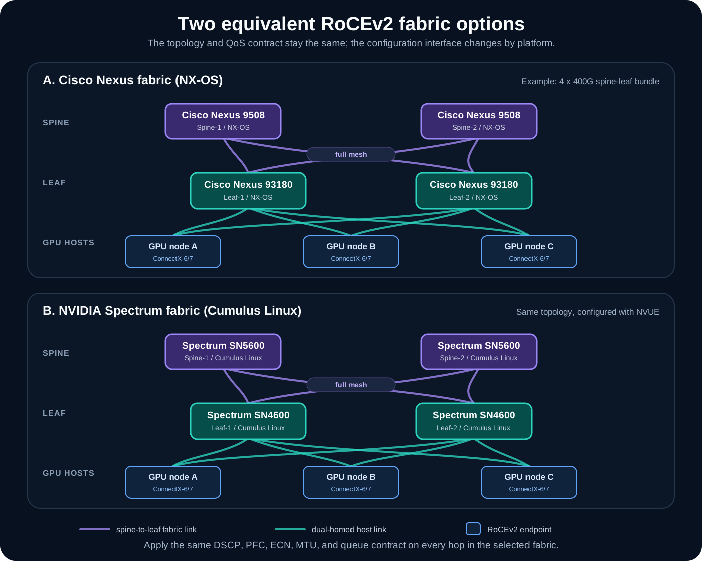
The diagram is intentionally role-based. Exact port speed, breakout, line-card support, oversubscription, and link count must be validated against the chosen hardware. The PDF’s example uses a full-mesh spine-to-leaf fabric with a 4 x 400G bundle.
1.1 External marking versus internal queue number
The values visible on the wire do not have to equal a switch’s local queue number. The cross-platform contract is the packet marking and lossless priority; each platform may map that contract into different internal objects.
| Traffic | On-wire marking | Lossless treatment | Scheduler goal |
|---|---|---|---|
| RoCEv2 data | DSCP 24; priority 3 after classification | PFC enabled on priority 3; ECN enabled on the RoCE data queue | Weighted bandwidth, 50-60% in these examples |
| CNP | DSCP 48; normally priority 6 on Cumulus/ConnectX | No PFC in this design | Strict priority so congestion feedback is not trapped behind data |
| Other traffic | DSCP 0 unless another policy applies | No PFC | Remaining weighted bandwidth |
The Cisco example maps DSCP 48 to QoS group 7 / output queue 7, while the Cumulus default maps DSCP 48 to switch priority 6 / traffic class 6. That difference is acceptable: both give CNP a strict egress queue, and the packet remains DSCP 48 across the routed fabric.
The source distills the design into four principles:
- CNP = strict priority — control-plane feedback, with a low-latency guarantee.
- RoCE data = weighted bandwidth (DWRR 60% in the Cisco example) — guaranteed throughput while the remainder stays available for other traffic.
- PFC only on CoS/priority 3 — lossless protection applies to the RoCE data class alone.
- ECN only on the RoCE traffic class — only RoCE participates in end-to-end congestion control.
1.2 What DSCP actually is
DSCP (Differentiated Services Code Point) is the upper six bits of the IP header’s ToS byte, giving 64 possible values. Switches classify on it: it decides which queue a packet enters and whether PFC and ECN apply to that packet.
| Value | Alias | Binary | Role in this design |
|---|---|---|---|
| 0 | BE (Best Effort) | 000000 | Ordinary TCP traffic, no special handling |
| 24 | CS3 (Class Selector 3) | 011000 | RoCEv2 data — the common industry convention, consistent across NVIDIA and Cisco documentation |
| 48 | CS6 (Class Selector 6) | 110000 | CNP congestion notification — must be delivered at the highest priority |
The mnemonic: DSCP 24 is the RoCE data channel, DSCP 48 is the congestion-signal channel; everything else takes the default path.
The values are not arbitrary. Under the conventional trust-DSCP mapping, the switch derives the internal priority from the upper three bits of the DSCP — priority = DSCP >> 3 — which slices the 64 values into eight blocks of eight, each anchored by a Class Selector (CS) codepoint. This is exactly the default mapping section 3.4 relies on (“DSCP 24–31 → switch priority 3, DSCP 48–55 → switch priority 6”), and it is why DSCP 24 (this guide) and DSCP 26 (common in NVIDIA documentation) land in the same queue:
| DSCP range | Class Selector | CS binary | Priority (DSCP » 3) | Typical use / role in this design |
|---|---|---|---|---|
| 0–7 | CS0 (0) | 000xxx | 0 | Best effort — everything unmarked |
| 8–15 | CS1 (8) | 001xxx | 1 | Scavenger / bulk background traffic |
| 16–23 | CS2 (16) | 010xxx | 2 | OAM / low-priority transactional |
| 24–31 | CS3 (24) | 011xxx | 3 | RoCEv2 data — DSCP 24 here, DSCP 26 in NVIDIA docs; PFC and ECN apply |
| 32–39 | CS4 (32) | 100xxx | 4 | Interactive video / real-time streams |
| 40–47 | CS5 (40) | 101xxx | 5 | Voice — EF (46) falls in this block |
| 48–55 | CS6 (48) | 110xxx | 6 | Network control — CNP (DSCP 48) in this design |
| 56–63 | CS7 (56) | 111xxx | 7 | Reserved for network control |
Two caveats keep this table honest. First, DSCP >> 3 is the default convention, not a law — every platform in this guide can override it (NX-OS with explicit match dscp class-maps in section 2.1, Cumulus with a custom mapping in section 3.4), and the Cisco template indeed puts CNP in queue 7 rather than 6. Second, the AF classes and EF also live inside these blocks (AF31 = 26 is in the CS3 block, EF = 46 in the CS5 block), so a fabric that carries voice or AF-marked traffic must check for collisions before borrowing a block for RoCE.
1.3 Why ECN should act before PFC
The intended congestion-control sequence is:
- A RoCE data queue begins to build.
- The switch marks ECN-capable packets with Congestion Experienced (CE).
- The receiving ConnectX notification point sends a CNP back to the sender.
- The sender’s reaction point reduces its DCQCN transmission rate.
- PFC pauses priority 3 only if the queue still approaches the lossless-buffer limit.
ECN and DCQCN provide end-to-end rate control. PFC is the hop-by-hop safety net. A healthy fabric can show ECN marks during congestion while PFC pause counters remain low.
1.4 DCBX: negotiating the contract instead of typing it twice
DCBX (Data Center Bridging Exchange) is the protocol directly connected Ethernet devices use to exchange and negotiate Data Center Bridging (DCB) settings. It runs as an extension of LLDP between neighbors:
Server NIC <-- LLDP/DCBX --> Ethernet switch
DCBX can advertise and coordinate:
- PFC — which Ethernet priorities receive lossless, per-priority pause behavior.
- ETS (Enhanced Transmission Selection) — how bandwidth is allocated among traffic classes.
- Application Priority — which priority an application should use, for example RoCEv2 traffic.
- Configuration willingness — whether a device accepts its neighbor’s advertised configuration (the “willing” bit).
In this document’s traffic contract, the arrangement DCBX would advertise is:
RoCE traffic -> DSCP 24 -> priority 3 -> PFC enabled
DCBX lets the switch tell a compatible NIC that RoCE should ride on priority 3 and that PFC is active for that priority.
DSCP 24 or DSCP 26? Vendor documentation frequently shows this example with DSCP 26 (NVIDIA’s docs in particular). Both values land in the same place: under the conventional
priority = DSCP >> 3mapping, the whole DSCP 24–31 block classifies to priority 3. This guide uses DSCP 24 end to end (see section 1.1); if your environment standardizes on 26, that is equally valid — just change every hop consistently, as with any other value in the contract.
Why it matters. If the NIC and the switch disagree about priority or PFC settings, the intended lossless traffic may enter the wrong queue, experience packet loss, trigger pause on an unintended priority, or contribute to congestion spreading and deadlock. DCBX keeps the two sides consistent — but it does not carry application traffic and does not itself make Ethernet lossless. It only exchanges DCB configuration.
Main variants:
- IEEE DCBX — standardized through IEEE 802.1Qaz; what modern equipment uses.
- CEE DCBX — the older pre-standard (Converged Enhanced Ethernet) variant.
- Vendor-specific implementations — may add proprietary behavior or commands.
Both neighbors must run compatible DCBX versions and modes, or negotiation silently fails and each side keeps its local settings.
DCBX versus LLDP:
| LLDP | DCBX | |
|---|---|---|
| Role | Discovers neighboring devices | Exchanges DCB settings |
| Advertises | Identity, port, capabilities | PFC, ETS, application priorities |
| Scope | General-purpose | Data-center / lossless-network focused |
DCBX is therefore best understood as DCB configuration negotiation carried inside LLDP messages.
Two practical notes for this guide:
- The templates below configure both ends explicitly and use
priority-flow-control mode onon the switch (section 2.5) rather thanauto, which would depend on DCBX negotiation. Static configuration on both ends is deterministic; if you rely on DCBX instead, verify what was actually negotiated, not just what was configured. On ConnectX hosts configured manually (section 4.3), make sure a runninglldpador firmware DCBX in willing mode is not silently overriding your settings. - In a virtual lab (SONiC-VS, vEOS-lab and similar), you can inspect LLDP/DCBX configuration and control-plane state, but a virtual switch has no ASIC — it cannot validate real buffering, PFC pause behavior, or RoCE performance.
1.5 End-to-end example: one RoCE packet through the QoS pipeline
Everything in sections 1.1–1.4 compresses into one packet walk. Suppose the network selects DSCP 24 for RoCE:
Application generates RoCEv2
              ↓
NIC marks IP packet DSCP 24
              ↓
Switch trusts DSCP
              ↓
DSCP 24 → internal TC 3
              ↓
        ┌─────┴─────┐
        ↓           ↓
Ingress PG 3     Egress Queue 3
        ↓           ↓
PFC priority 3   ETS/WRED/ECN
Note the fork: the internal traffic class feeds two independent mappings. On the ingress side it selects a priority group (PG) — the lossless buffer that PFC watches and defends. On the egress side it selects the output queue — where ETS (Enhanced Transmission Selection divides bandwidth among traffic classes while allowing unused bandwidth to be shared.) scheduling and WRED/ECN marking act. A misconfiguration can break one leg while the other looks healthy, which is why verification has to check both.
The complete policy, in one table:
| Function | Value |
|---|---|
| RoCE DSCP | 24 |
| DSCP name | CS3 |
| Internal TC | 3 |
| PCP/PFC priority | 3 |
| Ingress priority group | 3 |
| Egress queue | 3 |
| PFC | Enabled on priority 3 |
| ECN | Enabled using RoCE-specific thresholds |
Keeping TC, PG, queue, and PFC priority all at the same number is a convention, not a requirement — but breaking the symmetry without a reason is how the “wrong leg” bugs above are born.
Cumulus Linux: the pipeline comes from one command
On Cumulus this entire chain is generated by the default RoCE profile — nv set qos roce mode lossless (section 3.1). The generated state matches the table above: trust is pcp,dscp, DSCP 24–31 map to switch priority 3, PFC and ECN are enabled on traffic class 3, and the lossless buffer is carved automatically. Section 3.2 shows the full generated profile via nv show qos roce; you only touch the individual mappings when departing from the default contract (section 3.4).
SONiC: the same pipeline as CONFIG_DB tables
SONiC exposes each stage of the pipeline as an explicit CONFIG_DB table, which makes the packet walk unusually literal:
Ingress packet
      ↓
Trust DSCP or PCP
      ↓
DSCP_TO_TC_MAP / DOT1P_TO_TC_MAP
      ↓
Internal traffic class
      ├──→ TC_TO_PRIORITY_GROUP_MAP → ingress buffer/PG
      └──→ TC_TO_QUEUE_MAP          → egress queue
                                             ↓
                               scheduler + WRED/ECN
Useful live-configuration checks:
sudo sonic-cfggen -d --print-data | jq '.DSCP_TO_TC_MAP'
sudo sonic-cfggen -d --print-data | jq '.DOT1P_TO_TC_MAP'
sudo sonic-cfggen -d --print-data | jq '.TC_TO_QUEUE_MAP'
sudo sonic-cfggen -d --print-data | jq '.TC_TO_PRIORITY_GROUP_MAP'
sudo sonic-cfggen -d --print-data | jq '.MAP_PFC_PRIORITY_TO_QUEUE'
sudo sonic-cfggen -d --print-data | jq '.PORT_QOS_MAP'
sudo sonic-cfggen -d --print-data | jq '.WRED_PROFILE'
sudo sonic-cfggen -d --print-data | jq '.SCHEDULER'
The table names map one-to-one onto the diagram: DSCP_TO_TC_MAP/DOT1P_TO_TC_MAP are the trust step, TC_TO_PRIORITY_GROUP_MAP and TC_TO_QUEUE_MAP are the two legs of the fork, PORT_QOS_MAP binds the maps (and pfc_enable) to ports, and WRED_PROFILE/SCHEDULER are the egress stage. On SONiC-VS these tables are fully inspectable even though, per the caveat in 1.4, the virtual data plane cannot demonstrate real PFC or buffering behavior.
2. Cisco Nexus 9000 NX-OS template
The following configuration uses the eight-queue system classes from the source design. It is representative of Nexus 9300/9500 platforms on NX-OS 9.3 or later that support these MQC objects; it is not a universal paste-and-run template. Before applying it, inspect the active queue model and the system-defined class names:
show policy-map system type queuing
show class-map type network-qos
show module
show version
Cisco documents the dependencies and platform limitations in the current Nexus 9000 NX-OS Quality of Service Configuration Guide.
2.1 Classify RoCE data and CNP
! Recognize RoCE data by its on-wire marking: DSCP 24 (CS3)
class-map type qos match-all ROCE-DATA
  match dscp 24

! Recognize CNP congestion feedback: DSCP 48 (CS6)
class-map type qos match-all ROCE-CNP
  match dscp 48
This is L3 classification. If the ingress policy must trust an 802.1Q PCP value instead, use a match cos design and ensure the host actually transmits a VLAN tag. Do not mix DSCP and PCP assumptions silently.
2.2 Map ingress traffic to local QoS groups
! Ingress policy: translate the on-wire DSCP into internal QoS groups.
! The qos-group number selects which system queue the packet uses inside
! the switch - this is the "internal TC" step of the pipeline in 1.5.
policy-map type qos ROCE-INGRESS
  ! RoCE data -> QoS group 3 (will be lossless: PFC + ECN)
  class ROCE-DATA
    set qos-group 3
  ! CNP -> QoS group 7 (will be strict priority)
  class ROCE-CNP
    set qos-group 7
  ! Everything else -> QoS group 0 (best effort)
  class class-default
    set qos-group 0
QoS group 3 becomes the lossless data class. QoS group 7 becomes the strict CNP queue. QoS group 0 carries default traffic.
2.3 Configure egress scheduling and ECN
policy-map type queuing ROCE-EGRESS
  ! Queue 7 (CNP): strict priority - always serviced first, so congestion
  ! feedback is never stuck behind a burst of data
  class type queuing c-out-8q-q7
    priority level 1

  ! Queue 3 (RoCE data): guaranteed 60% of the bandwidth left after the
  ! strict queue, with WRED in ECN mode - between the two thresholds the
  ! switch MARKS packets instead of dropping them
  class type queuing c-out-8q-q3
    bandwidth remaining percent 60
    random-detect minimum-threshold 150 kbytes maximum-threshold 3000 kbytes drop-probability 7 weight 0 ecn

  ! Default queue: whatever bandwidth remains
  class type queuing c-out-8q-q-default
    bandwidth remaining percent 40
Reading the random-detect line term by term: marking starts once the queue passes the minimum threshold (150 KB), the marking probability climbs until the maximum threshold (3000 KB), drop-probability 7 is the probability ceiling reached at that maximum, weight 0 means the decision uses the instantaneous queue depth with no averaging, and the trailing ecn keyword is what turns the whole mechanism from “random early drop” into “random early mark” — remove it and WRED silently discards RoCE packets instead of marking them.
The 150 kbytes and 3000 kbytes values are example starting points from the source’s 100G design. They are not portable buffer percentages. Port speed, cable length, ASIC architecture, active-port count, shared-buffer policy, RTT, and traffic shape all influence a safe threshold.
Use these operational rules when tuning:
- If PFC transmit counters grow quickly before useful ECN feedback appears, ECN is probably too late.
- If ECN marking is continuous under moderate load and throughput collapses, the minimum threshold may be too low or DCQCN too aggressive.
- If queue depth reaches the buffer limit, the maximum threshold is too high, the CNP path is blocked, or the sender is not reacting.
- The source sizes the maximum threshold at or below roughly 80% of the port’s available buffer, and reads
drop-probability 7as a marking slope suited to long-lived elephant flows. - The thresholds are absolute byte values. On a different port speed (25G/100G/400G), scale them proportionally instead of copying.
2.4 Define the no-drop network class
policy-map type network-qos ROCE-NETWORK-QOS
  ! Network-QoS class nq3 = internal class 3 (the RoCE data class):
  ! jumbo MTU, and 'pause pfc-cos 3' makes it a no-drop class - the
  ! switch reserves lossless buffer and sends/honors PFC for CoS 3
  class type network-qos c-8q-nq3
    mtu 9216
    pause pfc-cos 3

  ! Default class: same jumbo MTU, but stays drop-eligible (no pause)
  class type network-qos c-8q-nq-default
    mtu 9216
The important invariant is qos-group 3 -> no-drop class -> pfc-cos 3. If those values do not align, PFC can be enabled on the interface yet fail to protect RoCE traffic.
2.5 Apply system and interface policies
! Switch-wide: the no-drop classes and the egress scheduler apply to the
! whole box, not per interface
system qos
  service-policy type network-qos ROCE-NETWORK-QOS
  service-policy type queuing output ROCE-EGRESS

! Per port: classify incoming traffic and enable PFC on the link
interface Ethernet1/1
  service-policy type qos input ROCE-INGRESS
  ! 'mode on' forces PFC regardless of DCBX negotiation (see section 1.4)
  priority-flow-control mode on
  ! Watchdog: detect a stuck-pause condition (PFC storm/deadlock) and recover
  priority-flow-control watch-dog-interval on
Repeat the ingress policy and PFC interface settings on every RoCE-facing host and fabric port. mode on gives deterministic behavior; auto depends on DCBX negotiation. Both ends of a lossless link must agree.
The watchdog command and behavior are release-specific. Confirm the supported PFC watchdog configuration and recovery action on the target platform rather than assuming the example is sufficient.
2.6 Full configuration template
The source’s complete template, assembled from the pieces above — intended for every spine and leaf (adjust the interface range):
! =====================================
! Cisco Nexus 9000 - RoCEv2 complete configuration
! Applies to all spines and leaves
! =====================================

! 1. Classification - recognize the two RoCE markings on ingress
!    DSCP 24 (CS3) = RoCE data, DSCP 48 (CS6) = CNP congestion feedback
class-map type qos match-all ROCE-DATA
  match dscp 24
class-map type qos match-all ROCE-CNP
  match dscp 48

! 2. Ingress QoS-group mapping - DSCP to internal class:
!    data -> group 3 (lossless), CNP -> group 7 (strict), rest -> group 0
policy-map type qos ROCE-INGRESS
  class ROCE-DATA
    set qos-group 3
  class ROCE-CNP
    set qos-group 7
  class class-default
    set qos-group 0

! 3. Egress queuing + ECN
!    q7 (CNP): strict priority, always serviced first
!    q3 (RoCE data): 60% of remaining bandwidth; WRED marks (ecn keyword)
!       instead of dropping between the 150 KB / 3000 KB thresholds
!    default queue: the remaining 40%
policy-map type queuing ROCE-EGRESS
  class type queuing c-out-8q-q7
    priority level 1
  class type queuing c-out-8q-q3
    bandwidth remaining percent 60
    random-detect minimum-threshold 150 kbytes
                  maximum-threshold 3000 kbytes
                  drop-probability 7
                  weight 0
                  ecn
  class type queuing c-out-8q-q-default
    bandwidth remaining percent 40

! 4. PFC network QoS - make internal class 3 a no-drop class:
!    reserve lossless buffer and send/honor PFC pause for CoS 3;
!    jumbo MTU on both classes
policy-map type network-qos ROCE-NETWORK-QOS
  class type network-qos c-8q-nq3
    mtu 9216
    pause pfc-cos 3
  class type network-qos c-8q-nq-default
    mtu 9216

! 5. System-level apply - no-drop classes and egress scheduler are
!    switch-wide settings
system qos
  service-policy type network-qos ROCE-NETWORK-QOS
  service-policy type queuing output ROCE-EGRESS

! 6. Interface-level apply - classification + PFC on every RoCE-facing
!    port; 'mode on' forces PFC without relying on DCBX, watchdog
!    detects and breaks stuck-pause (PFC storm) conditions
interface Ethernet1/1-48
  service-policy type qos input ROCE-INGRESS
  priority-flow-control mode on
  priority-flow-control watch-dog-interval on
2.7 Verify NX-OS
| Command | What to look at |
|---|---|
show policy-map type qos | Classification and the QoS-group mapping |
show policy-map type queuing | Queue scheduling and the ECN thresholds |
show policy-map type network-qos | The PFC (no-drop) configuration |
show policy-map system type queuing | Which policies are actually active system-wide |
show interface priority-flow-control | Per-interface PFC state (on/off) and pause counters |
show queuing interface ethernet 1/1 | Per-interface queue depth and ECN marking statistics |
show hardware qos class | Hardware QoS resource allocation |
Check both configuration and counters. An interface showing PFC on is not proof that DSCP 24 reaches the no-drop queue.
3. NVIDIA Spectrum with Cumulus Linux
Current Cumulus Linux provides a built-in RoCE profile through NVUE. Use NVUE for the complete configuration so validation and error handling remain intact.
3.1 Enable the lossless RoCE profile
sudo nv set qos roce mode lossless
sudo nv config apply
sudo nv config save
On a fresh configuration, nv set qos roce defaults to lossless. If the switch was previously placed in lossy mode, the shorter command does not change it back; specify mode lossless explicitly.
The current default lossless profile maps:
| Function | Cumulus default |
|---|---|
| RoCE data | Switch priority 3 -> traffic class 3 -> DWRR 50% |
| CNP | Switch priority 6 -> traffic class 6 -> strict priority |
| Other traffic | Traffic class 0 -> DWRR 50% |
| PFC | Tx and Rx enabled for switch priority 3 |
| ECN | RoCE queue, approximately 146.48 KB minimum / 1.43 MB maximum / probability 100 in the documented profile |
| Trust | PCP and DSCP |
| Application TLV | UDP 4791 -> priority 3 |
These defaults can differ by Cumulus release and Spectrum ASIC. NVIDIA explicitly warns that a RoCE configuration generated for one ASIC generation is not portable to another. See the current Cumulus Linux RoCE documentation.
3.2 Verify the generated profile
nv show qos roce
nv show interface swp16 qos roce status
nv show interface swp16 qos roce counters
nv show interface qos-roce-status
nv show interface qos-roce-counters
nv show qos congestion-control default-global
The source’s sample nv show qos roce output for the default lossless profile:
cumulus@switch:~$ nv show qos roce

                      operational      applied
state                                  enabled
mode                  lossless         lossless
pfc
  pfc-priority                         3
  rx-enabled                           enabled
  tx-enabled                           enabled
  cable-length                         100
congestion-control
  congestion-mode                      ECN
  enabled-tc                           0,3
  min-threshold                        146.48 KB
  max-threshold                        1.43 MB
  probability                          100
trust
  trust-mode                           pcp,dscp
Two details worth noticing in that output: enabled-tc 0,3 means ECN marking is active on the default traffic class 0 as well as the RoCE class 3, and cable-length 100 feeds the PFC headroom calculation — set it to the real cable length on long links.
Read the operational column, not only the applied configuration. On some Spectrum ASICs, the system-level ECN threshold and hardware-programmed interface threshold differ because the hardware rounds to supported units.
3.3 Optional single ingress pool
For a fabric dominated by bursty lossless AI traffic, Cumulus supports a shared ingress pool:
sudo nv set qos roce mode lossless-single-ipool
sudo nv config apply
This is not automatically better. A shared pool can absorb larger RoCE bursts, but it changes the isolation between lossy and lossless traffic. Keep the default separated pools when substantial lossy traffic must remain protected.
3.4 Custom DSCP mapping
The default mapping already places DSCP 24-31 in switch priority 3 and DSCP 48-55 in switch priority 6. If the fabric uses a different DSCP, create an explicit mapping instead of relying on range behavior:
sudo nv set qos mapping roce-custom trust l3
sudo nv set qos mapping roce-custom dscp 34 switch-priority 3
sudo nv set interface swp1-16 qos mapping profile roce-custom
sudo nv config apply
Using trust l3 makes DSCP authoritative. Use trust both only when the intended PCP-versus-DSCP precedence is understood for tagged and untagged traffic.
3.5 Custom ECN profile
The following example demonstrates the source’s 40000 / 200000 byte thresholds on traffic class 3. Treat them as test values, not recommended universal settings:
sudo nv set qos congestion-control roce-ecn traffic-class 3 min-threshold 40000
sudo nv set qos congestion-control roce-ecn traffic-class 3 max-threshold 200000
sudo nv set qos congestion-control roce-ecn traffic-class 3 probability 100
sudo nv set qos congestion-control roce-ecn traffic-class 3 ecn enable
sudo nv set interface swp1-16 qos congestion-control profile roce-ecn
sudo nv config apply
For sizing, the source suggests a minimum threshold near 50% and a maximum near 90% of the per-port buffer — on a 100G Spectrum-3 port with roughly 12 MB of buffer, that is about 6 MB / 10.8 MB. NVUE’s conservative defaults (146.48 KB / 1.43 MB) favor latency-sensitive traffic; raise the thresholds gradually under load tests rather than jumping to the ceiling.
Verify the profile before and after load testing:
# The custom ECN profile and its interface binding
nv show qos congestion-control roce-ecn
nv show interface swp16 qos congestion-control

# View RoCE status
nv show interface swp16 qos roce status
nv show interface swp16 qos roce counters
nv show qos congestion-control default-global

# All-ports overview
nv show interface qos-roce-status
nv show interface qos-roce-counters
3.6 Source leaf template with MLAG
The source’s full leaf template layers MLAG on top of the RoCE profile — peerlink, host-facing bond, and bridge membership. Note that its Cumulus templates use switch link MTU 9000 (nv set interface swp1-16 link mtu 9000 on the spine):
nv set qos roce

nv set interface peerlink bond member swp2-3
nv set mlag peer-ip linklocal
nv set mlag backup 192.168.200.12 vrf mgmt
nv set mlag mac-address 44:38:39:BE:EF:AA
nv set mlag priority 1000
nv set mlag init-delay 10

nv set interface bond1 bond member swp1
nv set interface bond1 bond mlag id 1
nv set interface bond1 link mtu 9000

nv set bridge domain br_default
nv set bridge domain br_default vlan 10,20,30
nv set interface bond1 bridge domain br_default
nv config apply
nv config save
For what each MLAG knob does — and the EVPN control plane that usually accompanies it — see the VXLAN EVPN lab guide.
4. Linux ConnectX host configuration
The host examples use:
Ethernet interface: ens1np0
RDMA device:        mlx5_1
RDMA port:          1
RoCE data DSCP:     24
PFC priority:       3
CNP DSCP/priority:  48 / 6
Replace these names after checking the actual PCI and RDMA topology.
The source’s stated requirements: ConnectX-4 or later, with MLNX_OFED v24+ or kernel 5.10+. The newer cc_params debugfs layout used in section 5 appears with MLNX_OFED v24+ / kernel 5.15+.
4.1 Confirm hardware and RoCEv2 mode
# Confirm the NIC model and firmware version
ibstat -d mlx5_1
lspci | grep -i -E 'Mellanox|NVIDIA'
rdma link show

# Check the RoCE mode (must be v2)
sudo cma_roce_mode -d mlx5_1 -p 1

# If the output is not RoCEv2:
sudo cma_roce_mode -d mlx5_1 -p 1 -m 2
The final command selects RoCEv2 for port 1 when the installed driver exposes cma_roce_mode. Verify the result on the exact MLNX_OFED or inbox-driver version.
4.2 Set RoCE data DSCP
The Linux sysfs value is the complete eight-bit traffic-class/TOS byte. DSCP occupies its upper six bits, so DSCP 24 is written as 24 << 2 = 96:
# DSCP 24 = 0x18 = binary 011000
# Note: the NIC expects the value already shifted left by 2 bits
# DSCP 24 -> write 96 (24 << 2 = 96)
echo 96 | sudo tee /sys/class/net/ens1np0/roce/dscp/1

# Verify
cat /sys/class/net/ens1np0/roce/dscp/1
For perftest, the equivalent TOS argument is -T 96.
Why the shift by 2?
This trips people up constantly, because Linux and the NIC use different representations of the same field.
DSCP is a 6-bit field. The IPv4 ToS byte it lives in is 8 bits, and the low two bits belong to ECN:
 bit7 bit6 bit5 bit4 bit3 bit2  bit1 bit0
+---------------------------------------+
|          DSCP (6 bits)      | ECN (2) |
+---------------------------------------+
So when someone says “DSCP 24”, they mean the 6-bit value 011000. But the byte on the wire is that value sitting in the upper six bits — with ECN 00, the byte is 01100000 = 0x60 = 96 decimal. The DSCP bits shifted left by two to make room for ECN:
DSCP value          011000        = 24
Byte in the header  01100000      = 96  (0x60)
                          ^^ ECN
Many NIC drivers — and Linux socket APIs such as setsockopt(IP_TOS) — do not ask for the 6-bit DSCP. They ask for the whole 8-bit ToS byte, which they write directly into the packet. Hence 96 rather than 24. The conversion is just a factor of four:
- DSCP to NIC value:
DSCP << 2(multiply by 4) - NIC value to DSCP:
NIC value >> 2(divide by 4)
| QoS class | DSCP | Value written to the NIC |
|---|---|---|
| Best Effort | 0 | 0 |
| AF21 | 18 | 72 |
| CS3 | 24 | 96 |
| AF31 | 26 | 104 |
| EF | 46 | 184 |
This is why a working configuration can look inconsistent at first glance: the switch policy and the design document talk about DSCP 24, while the host is configured with 96. Both describe the same packet.
Application marks DSCP 24
        |
        v
NIC writes ToS byte 96 (0x60)
        |
        v
Switch reads DSCP 24 from the upper 6 bits
        |
        v
Maps DSCP 24 -> priority 3
        |
        v
PFC priority 3, lossless queue
4.3 Set trust, priority mapping, scheduler, and PFC
Do not let lldpad and mlnx_qos compete for the same DCB state. This example uses OS-controlled QoS and direct mlnx_qos configuration:
# Disable lldpad (otherwise it overwrites the PFC and trust configuration)
sudo systemctl disable --now lldpad

# Trust DSCP, with QoS controlled by the OS rather than DCBX negotiation
sudo mlnx_qos -i ens1np0 --dcbx=os --trust=dscp

# Map DSCP to priority: RoCE data 24 -> 3, CNP 48 -> 6
sudo mlnx_qos -i ens1np0 --dscp2prio=set,24,3
sudo mlnx_qos -i ens1np0 --dscp2prio=set,48,6

# Priority-to-traffic-class mapping (identity mapping here)
sudo mlnx_qos -i ens1np0 -p 0,1,2,3,4,5,6,7

# Enable PFC on Cos 3 only (1 = enabled; the 8 digits are Cos 0-7)
sudo mlnx_qos -i ens1np0 -f 0,0,0,1,0,0,0,0

# Queue scheduling: TC 6 and 7 strict, TC 3 gets 50% of the ETS weight
sudo mlnx_qos -i ens1np0 \
  -s ets,ets,ets,ets,ets,ets,strict,strict \
  -t 10,10,10,50,10,10,0,0

# Verify
sudo mlnx_qos -i ens1np0
sudo mlnx_qos -i ens1np0 | grep -E "PFC|COS"
Reading the vectors — every one of them is eight values, indexed 0 through 7:
-f 0,0,0,1,0,0,0,0— the PFC vector. Only index 3 (the fourth position) is1, so PFC is enabled for Cos 3 alone. Every other priority stays lossy.-p 0,1,2,3,4,5,6,7— priority-to-traffic-class mapping, identity here: priority n goes to traffic class n.-sand-twork as a pair.-ssets each traffic class’s scheduler (etsorstrict), and-tgives the ETS bandwidth weights.strictoutranks everything, which is what guarantees CNPs are sent the moment they are generated;etsclasses then share the remainder by weight. In-t 10,10,10,50,10,10,0,0, traffic class 3 takes 50% while the strict classes carry weight0because a strict class does not draw from the ETS pool.
The net effect: CNP (traffic class 6) is served ahead of data and never paused by PFC, while RoCE data (traffic class 3) gets the lossless treatment and the bulk of the weighted bandwidth.
NVIDIA documents mlnx_qos options and driver interaction in the MLNX_OFED QoS guide.
4.4 Enable the ECN notification and reaction points
# Notification point: receiver sees CE and emits a CNP.
echo 1 | sudo tee /sys/class/net/ens1np0/ecn/roce_np/enable/3

# Reaction point: sender receives a CNP and reduces its rate.
echo 1 | sudo tee /sys/class/net/ens1np0/ecn/roce_rp/enable/3

# Mark CNP as DSCP 48 / priority 6.
echo 48 | sudo tee /sys/class/net/ens1np0/ecn/roce_np/cnp_dscp
echo 6  | sudo tee /sys/class/net/ens1np0/ecn/roce_np/cnp_802p_prio

cat /sys/class/net/ens1np0/ecn/roce_np/enable/3
cat /sys/class/net/ens1np0/ecn/roce_rp/enable/3
The two roles:
- NP (Notification Point) — the receiving side. When it sees a packet marked Congestion Experienced, it generates a CNP back toward the sender. Enable on every host.
- RP (Reaction Point) — the sending side. When it receives a CNP, it reduces its transmission rate under DCQCN. Enable on every host.
Both endpoint roles matter, and they are not alternatives. In a real fabric every server both sends and receives RoCE traffic, so each host acts as an NP for the flows it receives and an RP for the flows it sends — which is why both are enabled on every node, not split by role.
The values are per-priority, so the trailing /3 in the sysfs paths matters: it enables NP and RP for priority 3, the RoCE data class configured above. Enabling them on the wrong priority leaves the RoCE flows without congestion feedback. The CNP marking is set separately — cnp_dscp 48 and cnp_802p_prio 6 put the notification itself on the strict-priority CNP class, so the feedback is never queued behind the congested data it is trying to relieve.
The failure modes are asymmetric and worth recognizing:
- NP disabled on the receiver: the switch marks CE, but no CNP is ever generated. The sender never slows down, so the queue keeps growing until PFC takes over — you see rising PFC counters with no CNP activity.
- RP disabled on the sender: CNPs arrive but are ignored. Same outcome, different cause; distinguish the two by checking whether CNPs are actually on the wire.
4.5 MTU
The source uses host MTU 4200, with the switch side carrying jumbo frames (its Cisco template sets network-qos MTU 9216; its Cumulus templates set link MTU 9000 — both comfortably above the host’s 4200):
sudo ip link set dev ens1np0 mtu 4200
ip link show dev ens1np0
That accommodates a 4096-byte RDMA payload plus headers. A 9000-byte host MTU is also common. The requirements are simpler than the folklore: every L3 hop must carry the endpoint packet, and both communicating endpoints must use a compatible MTU. The switch’s 9216-byte system MTU is an envelope, not a requirement that the host also use exactly 9216.
4.6 Persist host settings
Many sysfs and mlnx_qos settings disappear after a reboot or driver reload. A systemd oneshot service can reapply the validated configuration.
/etc/systemd/system/roce-config.service:
[Unit]
Description=RoCEv2 host configuration
After=network-online.target
Wants=network-online.target

[Service]
Type=oneshot
RemainAfterExit=yes
ExecStart=/usr/local/sbin/roce-config.sh

[Install]
WantedBy=multi-user.target
/usr/local/sbin/roce-config.sh:
#!/usr/bin/env bash
# Reapply the RoCEv2 host configuration after a reboot or driver reload.
# sysfs and mlnx_qos settings are not persistent on their own.
set -euo pipefail

IFACE=ens1np0
RDMA_DEV=mlx5_1
RDMA_PORT=1

# RoCEv2 mode (-m 2) for RDMA-CM connections
cma_roce_mode -d "$RDMA_DEV" -p "$RDMA_PORT" -m 2

# RoCE data marking: DSCP 24, written as the full ToS byte (24 << 2 = 96)
echo 96 > "/sys/class/net/$IFACE/roce/dscp/$RDMA_PORT"

# Trust DSCP, OS-controlled QoS rather than DCBX negotiation
mlnx_qos -i "$IFACE" --dcbx=os --trust=dscp

# DSCP to priority: RoCE data 24 -> 3, CNP 48 -> 6
mlnx_qos -i "$IFACE" --dscp2prio=set,24,3
mlnx_qos -i "$IFACE" --dscp2prio=set,48,6

# Priority to traffic class (identity mapping)
mlnx_qos -i "$IFACE" -p 0,1,2,3,4,5,6,7

# PFC on Cos 3 only
mlnx_qos -i "$IFACE" -f 0,0,0,1,0,0,0,0

# Scheduling: TC 6 and 7 strict, TC 3 takes 50% of the ETS weight
mlnx_qos -i "$IFACE" \
  -s ets,ets,ets,ets,ets,ets,strict,strict \
  -t 10,10,10,50,10,10,0,0

# ECN notification point (send CNP on CE) and reaction point (slow down on CNP),
# both for priority 3; CNPs themselves are marked DSCP 48 / priority 6
echo 1  > "/sys/class/net/$IFACE/ecn/roce_np/enable/3"
echo 1  > "/sys/class/net/$IFACE/ecn/roce_rp/enable/3"
echo 48 > "/sys/class/net/$IFACE/ecn/roce_np/cnp_dscp"
echo 6  > "/sys/class/net/$IFACE/ecn/roce_np/cnp_802p_prio"

# Host MTU (the switch side carries jumbo frames)
ip link set dev "$IFACE" mtu 4200
Note that lldpad is not disabled here — that is a one-time systemctl disable from section 4.3, which persists on its own. If your image re-enables it, add the disable to this script too.
After reviewing the paths and names:
sudo chmod 0755 /usr/local/sbin/roce-config.sh
sudo systemctl daemon-reload
sudo systemctl enable --now roce-config.service
sudo systemctl status roce-config.service
5. DCQCN tuning
DCQCN parameters control how quickly a ConnectX sender reduces and restores its rate after CNPs. Driver versions expose parameters in different locations:
# Newer MLNX_OFED / kernels - substitute the PCI BDF.
/sys/kernel/debug/mlx5/0000:03:00.0/cc_params/

# Older per-interface layout.
/sys/class/net/ens1np0/ecn/roce_rp/params/
/sys/class/net/ens1np0/ecn/roce_np/params/
Find the PCI directory instead of copying a BDF:
ls /sys/kernel/debug/mlx5/
Core reaction-point parameters include:
| Parameter | Default | Source’s suggestion | Effect |
|---|---|---|---|
rp_ai_rate | 10 Mbps | 10-50 | Additive rate increase when congestion is absent |
rp_hai_rate | 50 Mbps | 50-200 | Faster hyper-additive recovery after congestion clears |
rp_min_dec_fac | 2% | 2-10% | Minimum rate-decrease factor after a CNP |
rp_time_reset | 1464 us | 1500-3000 | Timer used to advance rate recovery |
rp_byte_reset | 150000 | 150000 | Byte counter used to advance rate recovery |
rp_gd | 8 (log2) | 8-11 | Gain controlling how strongly alpha affects rate reduction |
rp_min_rate | 0 | 0 | Lower bound for the reduced transmission rate |
rp_rate_to_set_on_first_cnp | 0 | 0 | Rate to jump to on the first CNP (0 = disabled) |
rp_clamp_tgt_rate | 0 | 0 | Clamp the target rate to the current rate on decrease |
rp_clamp_tgt_rate_ati | 0 | 1 | Whether timer-based increase can clamp the target rate |
rp_rate_reduce_monitor_period | 0 | 500 | Minimum interval between rate-reduction actions (us) |
rp_initial_alpha_value | 128 | 128 | Starting congestion-estimate alpha (0-1024) |
rp_dce_tcp_g | 0.0078125 | default | Alpha update gain |
rp_dce_tcp_rtt | 50000 us | 50000 | Alpha update interval |
The source provides this AI-fabric example:
DEV=0000:03:00.0
CC_PATH="/sys/kernel/debug/mlx5/$DEV/cc_params"

echo 50   | sudo tee "$CC_PATH/rp_ai_rate"
echo 200  | sudo tee "$CC_PATH/rp_hai_rate"
echo 5    | sudo tee "$CC_PATH/rp_min_dec_fac"
echo 2000 | sudo tee "$CC_PATH/rp_time_reset"
echo 1    | sudo tee "$CC_PATH/rp_clamp_tgt_rate_ati"
Do not treat those values as universal recommendations. Confirm each file’s accepted range and units in the installed driver documentation. Tune in this order:
- Start with the driver defaults.
- Tune switch ECN thresholds so marking happens before PFC.
- Adjust one DCQCN parameter group at a time.
- Re-run the same incast or all-to-all workload after every change.
- Track throughput, tail latency, ECN marks, CNP rate, PFC frames, queue watermarks, and drops together.
- Watch
ethtool -S <interface> | grep -i pfcwhile tuning: frequent PFC means the ECN threshold or DCQCN still needs work. Section 6.5 lists the other counter sources. - Prefer ECN-threshold tuning first — in most fabrics it pays more than adjusting DCQCN parameters.
6. End-to-end validation
6.1 Verify link and MTU first
ibstat -d mlx5_1
rdma link show
ethtool ens1np0
ping -M do -s 4172 <peer-ip>
For a 4200-byte IPv4 MTU, an ICMP payload of 4172 bytes plus the 20-byte IP and 8-byte ICMP headers exercises the full MTU without fragmentation.
6.2 Verify the marking on the wire
sudo tcpdump -i ens1np0 -nn -vv 'udp port 4791'
DSCP 24 appears as TOS/traffic-class byte 0x60 before ECN bits are added. If the host marks correctly but the next switch classifies the flow into the default queue, the switch trust or ingress mapping is wrong.
6.3 Run an RDMA load test
# Server (Host-A)
ib_send_bw -d mlx5_1 --report_gbits -F --run_infinitely -R -T 96

# Client (Host-B)
ib_send_bw -d mlx5_1 --report_gbits -F --run_infinitely -R -T 96 <Host-A-IP>

# Expected result (100G NIC)
#   BW near 95+ Gb/s, without oscillation
#   PFC triggers rare or zero
What each flag contributes:
| Flag | Purpose |
|---|---|
-d mlx5_1 | The RDMA device to test — not the Ethernet interface name |
--report_gbits | Report in Gb/s rather than MB/s, so the result compares directly against line rate |
-F | Suppress the CPU-frequency warning (still set the governor to performance) |
--run_infinitely | Run continuously, so you can watch counters evolve rather than reading one snapshot |
-R | Connect through RDMA-CM — required for -T to take effect |
-T 96 | Mark the traffic with ToS 96, i.e. DSCP 24 — the value the whole fabric is configured for |
The -R -T 96 pair is the point of the whole test: without it, perftest sends unmarked traffic that lands in the default queue, so it exercises neither PFC nor ECN and tells you nothing about the lossless configuration. Both sides must use identical options.
Run it while watching the switch and host counters from section 6.4 — a test that only reports bandwidth confirms the link works, not that the lossless path is correct.
For a clean 100G link, the source’s expectation is 95+ Gb/s sustained without oscillation, and PFC triggers rare or zero. During steady non-congested traffic, PFC counters should be zero or nearly zero. During controlled congestion, ECN/CNP activity should appear before sustained PFC.
See the local perftest RDMA benchmarking guide for test selection and interpretation.
6.4 Monitor the complete path
These five are the primary load-test signals, with the thresholds the source uses:
| Metric | Healthy | Warning sign, and what it points to |
|---|---|---|
| PFC pause counters (priority 3) | Near zero — occasional brief bursts under load are acceptable | Continuously rising → the ECN threshold is too high, or DCQCN is reducing the rate too slowly |
| RDMA bandwidth utilization | Above 95% of line rate, stable and non-oscillating | Below 80% → the ECN threshold is too low, or the rate decrease is too aggressive |
| ECN marking counters | Present while queues build, but not continuous | Continuous heavy marking → the ECN minimum threshold is too low |
| Queue depth / watermark | Well below the lossless buffer limit | Approaching the buffer ceiling → raise the ECN threshold so marking starts earlier |
| Packet drops | Zero in the no-drop class | Any drops → asymmetric PFC configuration, or an MTU mismatch somewhere on the path |
Note the tension between rows one and two: PFC counters and throughput are tuned against each other. Pushing the ECN threshold down suppresses PFC but costs bandwidth if it overshoots; pushing it up recovers bandwidth until PFC starts firing. The target is the band where PFC is near zero and throughput is above 95% — if you cannot find it, the buffer or the DCQCN parameters are the constraint, not the threshold.
Alongside those, three configuration signals worth watching:
| Metric | Healthy | Warning sign, and what it points to |
|---|---|---|
| Endpoint link | Active RDMA port at the expected speed and MTU | Link fallback, MTU mismatch, wrong GID or RoCE mode |
| DSCP on the wire | RoCE data carries DSCP 24, CNP carries DSCP 48 | DSCP 0, or remarking at an intermediate hop |
| CNP activity | CNPs follow CE marks, and the sender’s rate responds | CE marks with no CNP → the receiver’s NP is disabled; CNPs with no rate change → the sender’s RP is disabled |
6.5 Where to read these counters
The tables above say what to watch; these are the commands that produce the numbers. Note first what does not: perftest reports throughput and message rate only — no PFC, ECN or CNP counters appear in its output, so a passing bandwidth test says nothing about whether the lossless path is working.
| Where | Command | What it shows |
|---|---|---|
| Host NIC | ethtool -S ens1np0 | grep -i -E 'pause|prio' | rx/tx_pause_ctrl_phy and per-priority counters such as prio3_tx_pause |
| Host NIC | mlnx_qos -i ens1np0 | PFC enabled state per priority, trust mode, and the scheduler configuration |
| Host RDMA | ls /sys/class/infiniband/mlx5_1/ports/1/hw_counters/ | np_cnp_sent, rp_cnp_handled, np_ecn_marked_roce_packets, out_of_buffer |
| During a test | ib_send_bw ... -W hw_counters/np_cnp_sent | The change in the named counters across the run |
| Cisco | show interface priority-flow-control | Per-interface PFC state and pause counts |
| Cumulus | nv show interface swp1 counters qos | The PFC, ingress-buffer and egress-queue sections |
| Cumulus | nv show interface swp1 qos roce counters | RoCE-specific ECN and CNP counts |
| Arista | show priority-flow-control counters | RxPFC and TxPFC per interface |
The hw_counters directory is the most useful entry here, because it answers the CNP row of the previous table entirely from the host: np_cnp_sent shows the receiver generating CNPs in response to CE marks, and rp_cnp_handled shows the sender acting on them. If the first is climbing and the second is not, the reaction point is the problem. This needs no switch access at all — valuable when you do not have credentials on the fabric.
Exact counter names vary by driver and firmware version, so grep for the concept rather than assuming a name. And note that Soft-RoCE (rxe) has none of these: with no hardware NIC and no lossless switch in the path, the pause and CNP counters do not exist. A lossless configuration cannot be validated in a software-RoCE lab — see the perftest guide for what such a lab does and does not prove.
For the Arista equivalents of the switch-side commands, including the PFC watchdog counters, see RoCEv2 lossless configuration on Arista EOS.
7. Troubleshooting order
Diagnose from the bottom up:
- Link: confirm port state, speed, optics, and
ibstat. - MTU: verify a non-fragmented probe across the routed path.
- RoCE mode: confirm RoCEv2 and the correct GID/interface.
- DSCP: capture packets and confirm DSCP 24 on data and 48 on CNP.
- Classification: prove DSCP reaches the intended internal priority and queue on every switch.
- PFC: verify priority 3 at both ends of every link; look for asymmetry.
- ECN/CNP: correlate switch CE marks with endpoint CNP and rate response.
- Load: run a controlled
perftestworkload before testing a distributed training job.
| Symptom | Likely direction | Corrective action |
|---|---|---|
| RDMA bandwidth is low but PFC is quiet | ECN too aggressive, DCQCN recovery too slow, or path issue | Inspect ECN marks, queue depth, routing, and DCQCN before enabling more PFC |
| PFC transmit counters rise continuously | ECN too late, receiver cannot drain, or sender ignores CNP | Lower/test ECN threshold, verify NP/RP and CNP strict queue |
| Switch drops RoCE packets | Wrong no-drop mapping, asymmetric PFC, or MTU mismatch | Trace DSCP -> priority -> queue -> PFC on both ends of every hop |
| RoCE connection fails | Wrong RoCE mode, GID, route, DSCP trust, or ACL | Verify cma_roce_mode, rdma link, underlay reachability, and UDP 4791 path |
| Throughput oscillates | DCQCN decrease/recovery is too aggressive | Return to defaults and tune one rate-control parameter at a time |
| Settings vanish after reboot | Host configuration was not persisted | Enable and validate the systemd oneshot service |
8. Cross-vendor considerations
A Cisco spine and NVIDIA leaf can interoperate technically because DSCP, ECN, PFC, and Ethernet framing are standards-based. The operational cost is higher:
- Internal queue IDs and show commands differ.
- Buffer thresholds use different units and hardware rounding.
- DCBX defaults and LLDP application TLVs may differ.
- PFC watchdog behavior is platform-specific.
- A threshold that works on one ASIC is not automatically safe on another.
If possible, keep a lossless pod operationally consistent. When mixing platforms, document the on-wire contract separately from each device’s local queue implementation.
9. Final checklist
- All endpoints use RoCEv2 on the intended RDMA port.
- RoCE data is DSCP 24 end to end.
- CNP is DSCP 48 and reaches a strict, non-PFC queue.
- DSCP 24 maps to lossless priority 3 on every switch and NIC.
- PFC is enabled only for the intended lossless priority.
- ECN marks the RoCE data queue before the PFC threshold.
- Host NP and RP functions are both enabled.
- MTU is compatible on both endpoints and every routed hop.
- PFC, ECN, CNP, queue, drop, and throughput counters are monitored together.
- Host QoS settings survive reboot and driver reload.
- Production thresholds were derived from load tests on the actual ASIC and link speed.
The central lesson is simple: a RoCEv2 configuration is one distributed control system. Switch classification, switch buffers, lossless priorities, endpoint marking, and DCQCN must be validated as a single path. Configuring any one layer in isolation can produce a link that looks correct while failing under congestion.