
SFP, QSFP, Fiber Types
Choosing an optical transceiver is harder than matching the number printed on the switch port. A working link has to align the form factor, host lane rate, Ethernet standard, optical organization, fiber type, connector, wavelength, FEC mode, loss budget, and platform support at both ends.
The first clarification is terminology: SFP is a specific one-lane form factor, not the general name for every removable optic. Engineers often say “SFP” informally, but 400G and 800G modules are normally QSFP112, QSFP-DD, QSFP-DD800, or OSFP.
This article builds the subject from ordinary SFP modules and OM/OS fiber through modern 400G and 800G optics, including representative models, photographs, lane arithmetic, breakout behavior, and a practical selection workflow.
Table of contents
1. Read every transceiver name in layers
A label such as QDD-400G-DR4-S describes several independent properties:
| Layer | Example | What it tells you |
|---|---|---|
| Form factor | SFP+, SFP28, QSFP28, QSFP-DD, OSFP | The physical cage, electrical connector, lane count, power envelope, and cooling model |
| Aggregate Ethernet rate | 10G, 100G, 400G, 800G | The nominal MAC-layer capacity |
| Optical class | SR, DR, FR, LR, ER, ZR | Approximate reach and optical technology |
| Optical lane count | 4, 8 | Parallel fibers or WDM wavelengths, depending on the standard |
| Breakout organization | 2X400G, 4X100G, 8X100G | Independent subports exposed by the module |
| Vendor suffix | -S, -I, P | Vendor-specific temperature, connector, feature, or product-class information |
Do not infer the speed from appearance. A 1G SFP, 10G SFP+, and 25G SFP28 can use nearly identical metal housings and duplex-LC fronts.
2. What the hardware looks like
2.1 Standard optical SFP
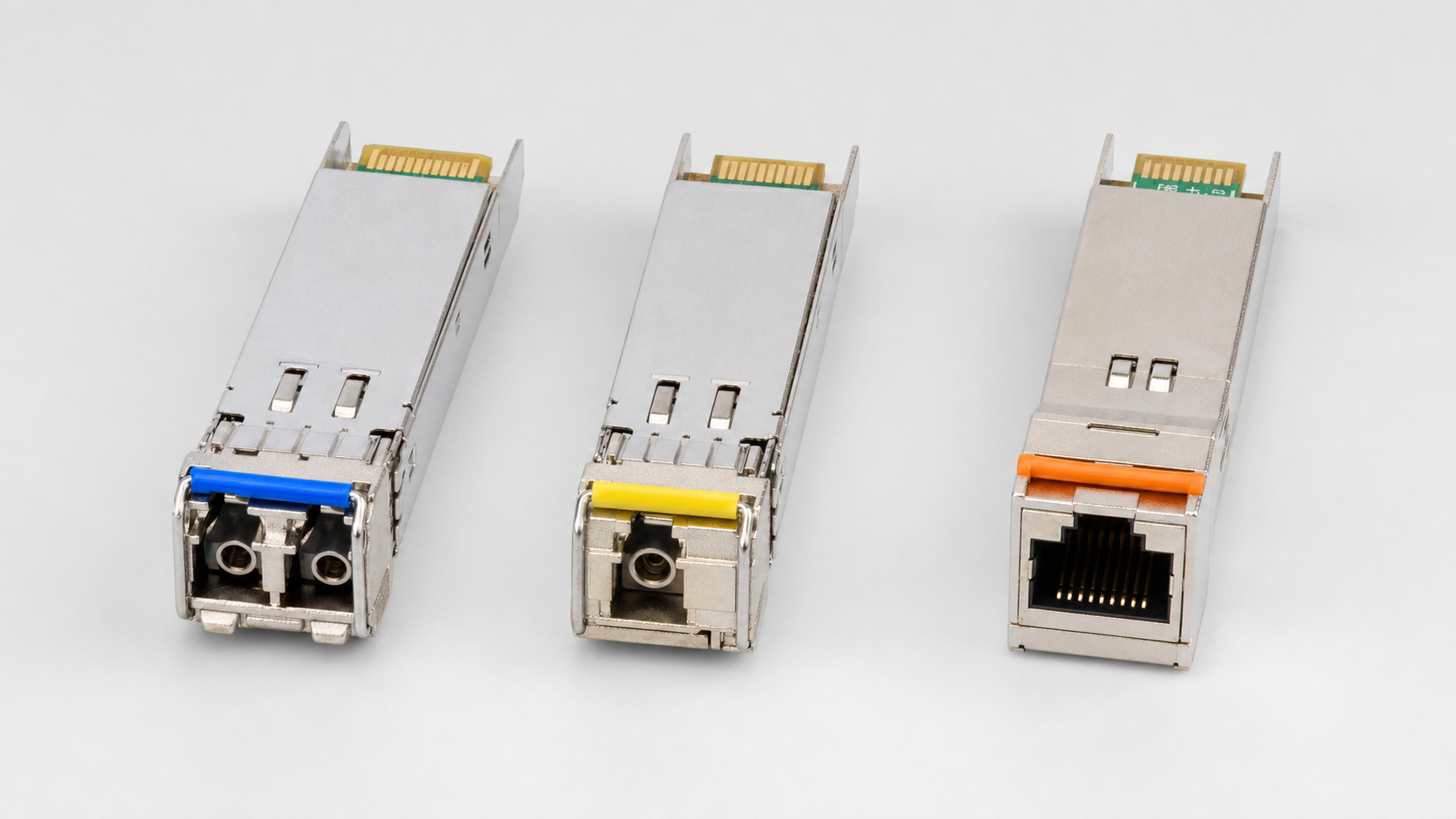
The image is an illustrative physical comparison, not a speed or part-number guide. SFP, SFP+, and SFP28 can use nearly identical housings.
| Photo position | Front interface | What it tells you | What it does not tell you |
|---|---|---|---|
| Left | Duplex LC | Separate transmit and receive fibers; common on SR/LR and many WDM optics | Rate, reach, wavelength, or fiber grade |
| Center | Simplex LC | A likely BX/BiDi optic using one fiber | The complementary transmit/receive wavelength pair |
| Right | Shielded RJ45 | A twisted-pair copper module | Supported rate, reach, or host power limits |
The left-hand example is the classic optical SFP-family module: narrow, with two small LC openings for transmit and receive. SX/SR multimode and LX/LR single-mode models may look the same externally. Read the label or module EEPROM rather than relying on pull-tab color.
2.2 Copper RJ45 SFP
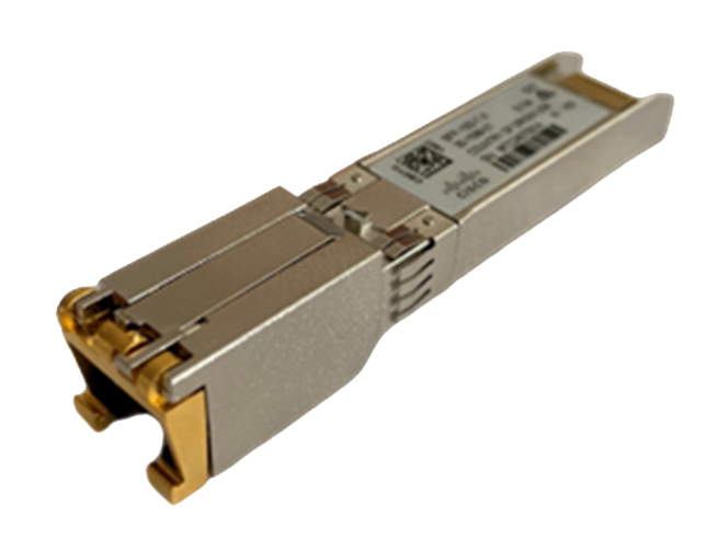
The right-hand module replaces the optical receptacle with a shielded twisted-pair Ethernet socket. A 1G 1000BASE-T SFP commonly supports 100 m, while a 10GBASE-T SFP+ may be limited to about 30 m and consume substantially more power. Cisco’s current 1G SFP documentation and 10G SFP+ documentation are useful examples of the power and reach differences.
A real copper module for comparison — note the shielded RJ45 front and the classic narrow SFP body:
2.3 Bidirectional and Compact SFPs
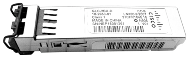
The center module illustrates a common BX/BiDi optic: one simplex LC port sends the two directions on different wavelengths over one strand. A Compact SFP is a denser variant that can place two single-fiber BiDi channels in one SFP-width assembly. BiDi optics must be installed as complementary pairs: for example, an upstream unit transmitting at one wavelength connects to a downstream unit transmitting at the other.
A real Compact SFP — Cisco’s GLC-2BX-D, two downstream BiDi channels in one SFP-width module, with both simplex LC openings visible at the front:
2.4 DAC and AOC assemblies
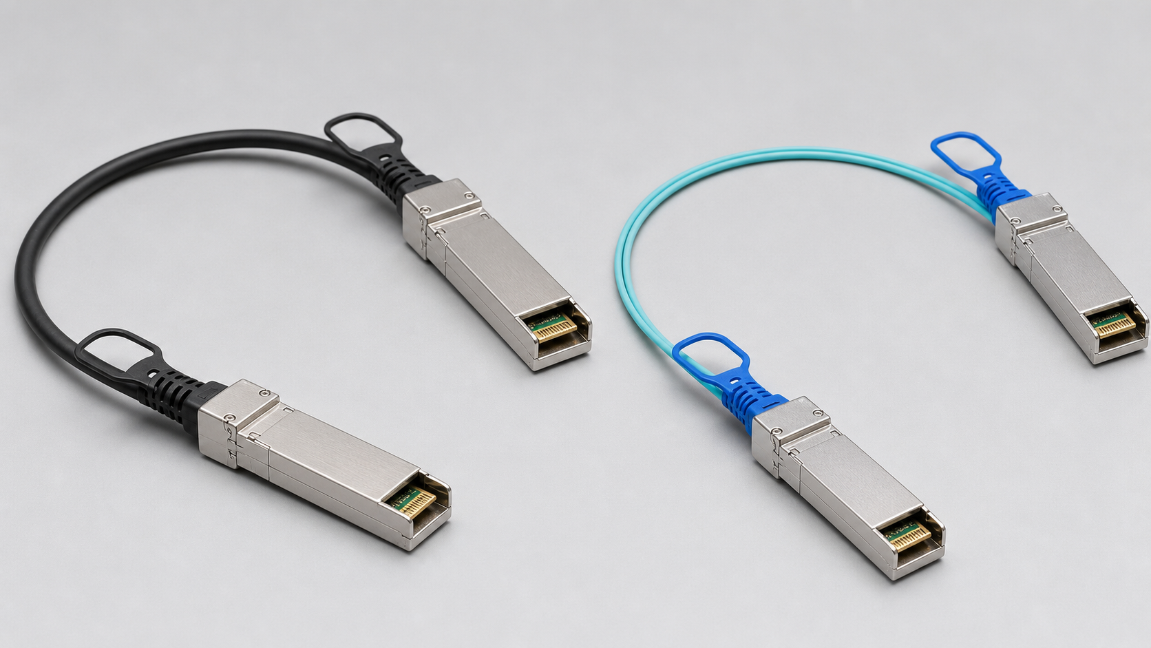
| Physical clue | Passive DAC, left | AOC, right |
|---|---|---|
| Cable between the ends | Thick copper twinax | Thin optical fiber |
| Conversion electronics | Normally none in a passive DAC | Electrical-to-optical conversion inside each end |
| Typical fit | Shortest, lowest-power in-rack links | Longer links and easier cable routing |
| Field replacement | Replace the complete captive assembly | Replace the complete captive assembly |
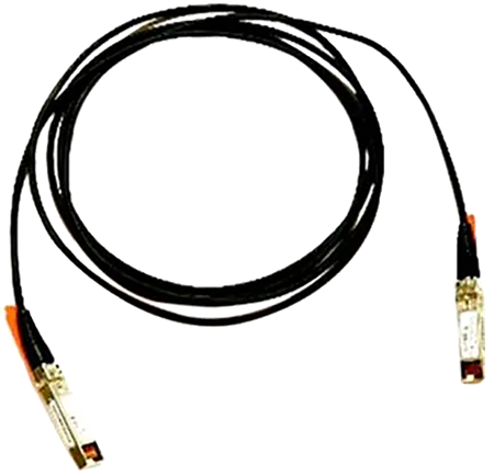
The left-hand direct-attach cable (DAC) is twinax copper with the transceiver ends permanently attached. Passive DAC is normally the lowest-power, lowest-cost choice for a short in-rack link.
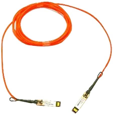
The right-hand active optical cable (AOC) also has permanently attached ends, but the cable between them is fiber. It is thinner and easier to route than twinax and can reach farther, but a damaged connector normally requires replacing the complete assembly.
The real products, for the same physical clues — thick black twinax on the DAC, thin colored fiber on the AOC, captive SFP+ ends on both:
Ordering check: Confirm the connector form at both ends, line rate, cable length, breakout mapping, and host-platform qualification. DAC and AOC ends are captive; they do not accept separate patch cords.
2.5 QSFP is visibly wider
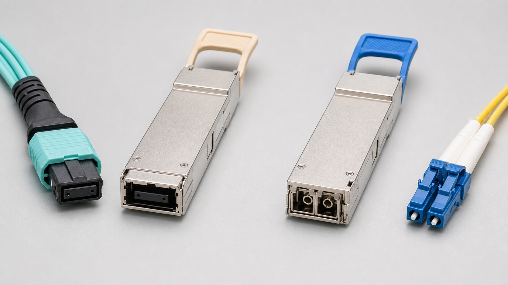
The QSFP28 body is visibly wider than SFP because it carries four host electrical lanes. The front connector, however, depends on the optical organization.
| Photo pair | Front interface | Typical 100G class | Cable clue |
|---|---|---|---|
| Left | MPO family | SR4; the same shell is also used by PSM4 variants | Aqua normally suggests OM3/OM4 multimode for SR4 |
| Right | Duplex LC | CWDM4 or LR4 | Yellow normally suggests OS2 single-mode |
The image is for physical recognition only. The MPO shell rendering does not establish MPO-12 population, key orientation, polarity, or male/female pinning. The same QSFP28 metal body and connector family can carry different reach, wavelength, and fiber specifications, so verify the module label and EEPROM.
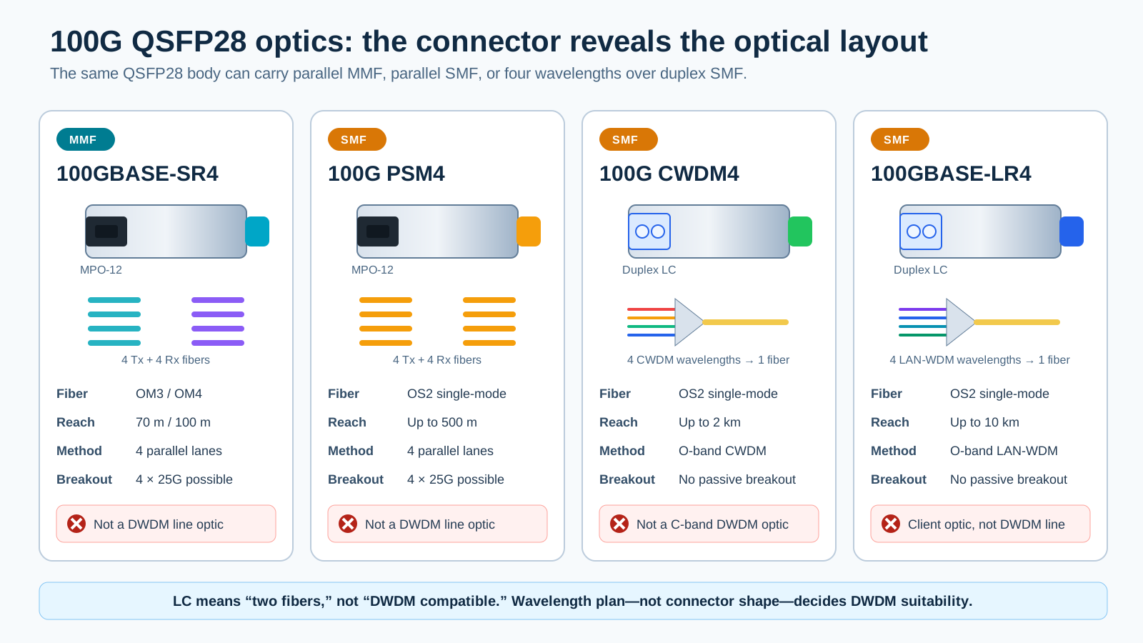
The diagram makes the front-interface difference explicit: SR4 and PSM4 use parallel fibers through MPO, while CWDM4 and LR4 multiplex four optical wavelengths onto a duplex-LC pair.
LC does not automatically mean DWDM. The 100G CWDM4 and LR4 wavelengths are client-side O-band wavelength plans, not tunable C-band ITU-grid line channels.

A QSA adapter places a one-lane SFP/SFP+/SFP28 module in a four-lane QSFP cage. It only works when the switch supports the lower rate and the required lane mapping on that port.
3. Form factors from 1G through 800G
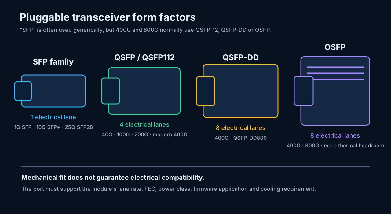
| Form factor | Common Ethernet rates | Host lanes | Typical role |
|---|---|---|---|
| SFP | 100M/1G | 1 | Access and legacy links |
| SFP+ | 10G | 1 | Server, storage, aggregation, DAC and AOC |
| SFP28 | 25G | 1 | Server access and leaf connectivity |
| SFP56 | 50G | 1 × 50G PAM4 | Newer server and switch links |
| QSFP+ | 40G | 4 × 10G | Four-lane aggregation and breakout |
| QSFP28 | 100G | 4 × 25G | Data-center uplinks and 4×25G breakout |
| QSFP56 | 200G | 4 × 50G PAM4 | Modern spine/leaf fabrics |
| QSFP112 | 400G | 4 × approximately 100G PAM4 | NICs and modern AI/HPC switches |
| QSFP-DD | 400G | Commonly 8 × approximately 50G PAM4 | Dense 400G switch and router ports |
| QSFP-DD800 | 800G | 8 × approximately 100G PAM4 | Dense 800G client and coherent optics |
| OSFP | 400G/800G | 8 lanes | Larger module with greater thermal headroom |
The QSFP-DD MSA defines eight-lane QSFP-DD, QSFP-DD800, and newer generations. A QSFP-DD cage is mechanically designed to accept earlier four-lane QSFP modules, but the host still decides which electrical rates, protocols, FEC modes, and module power classes are supported. OSFP is a different physical format and does not fit a QSFP-DD cage.
3.1 The same families in physical form
The diagram above shows relative sizes; these product photographs show what the major families actually look like in hand. The SFP-family body is pictured in section 2; QSFP112 is pictured in section 5.1.
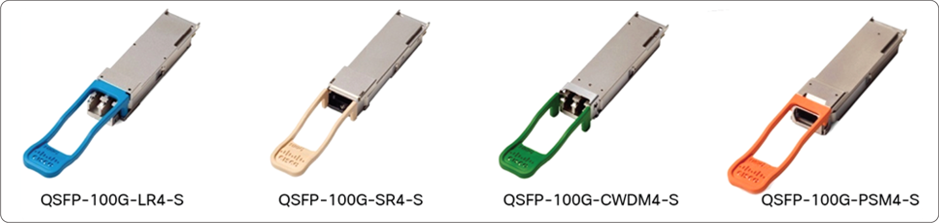
QSFP28 (100G) — four real Cisco modules. The body is identical across all four; only the front interface (duplex LC on LR4/CWDM4, MPO on SR4, and PSM4’s MPO behind the orange tab) and the optics inside differ. The colored pull tabs are a vendor convention for the optical class — helpful in a crowded switch faceplate, but never a substitute for reading the label:
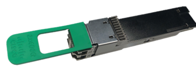
QSFP-DD800 (800G) — same width as QSFP28, but look at the rear: the second, deeper row of host contacts is the “double density” that carries eight electrical lanes. This 2×400G-FR4 unit shows its twin duplex-LC front and a green pull tab labeled with the breakout mode:
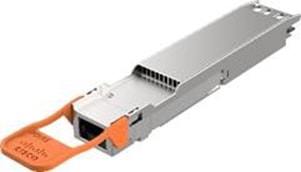
OSFP (400G/800G) — visibly wider and deeper than the QSFP family, with the integrated heat sink ridges on top that give it its thermal headroom. It requires its own cage; it does not fit QSFP-DD ports:
4. Fiber types: multimode and single-mode
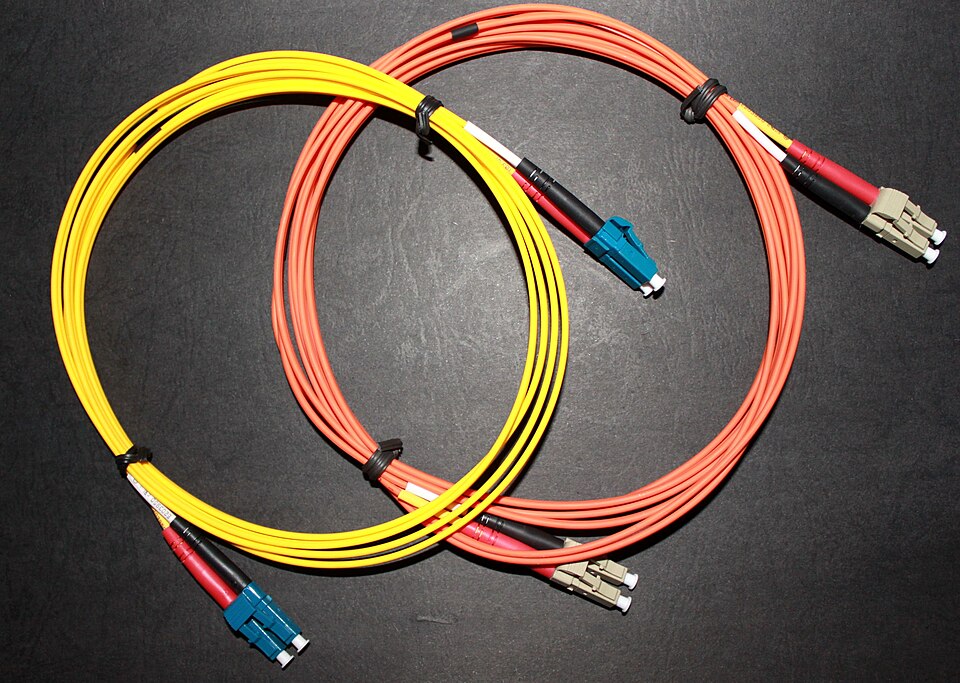
Jacket color is a useful clue, not proof. Read the printed cable type because installations are often inconsistent and regional conventions vary.
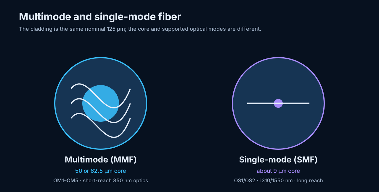
4.1 Multimode fiber
Multimode fiber has a larger core. Multiple optical paths propagate through it, producing modal dispersion that limits reach as data rate increases.
| Grade | Core/cladding | Common color clue | Practical position |
|---|---|---|---|
| OM1 | 62.5/125 µm | Orange | Legacy; unsuitable for most new high-speed designs |
| OM2 | 50/125 µm | Orange | Improved legacy multimode |
| OM3 | 50/125 µm | Aqua | Laser-optimized baseline for many 10G–100G links |
| OM4 | 50/125 µm | Aqua or violet | Higher bandwidth and longer SR/VR reach |
| OM5 | 50/125 µm | Lime green | Wideband MMF for shortwave wavelength multiplexing |
OM5 does not automatically extend every ordinary 850 nm SR link. The optic must use the wideband capability.
4.2 Single-mode fiber
Single-mode fiber has an effective core near 9 µm and supports one spatial mode. It is used with approximately 1310 nm client optics and 1550 nm/DWDM coherent systems.
| Grade | Common color clue | Typical use |
|---|---|---|
| OS1 | Yellow | Indoor, premises, often tight-buffered construction |
| OS2 | Yellow | Low-loss campus, outside plant, data-center interconnect and long haul |
The Fiber Optic Association maintains a useful comparison of OM and OS fiber types, including core sizes, attenuation, bandwidth, and color-code references.
5. Connector types matter as much as the fiber
5.1 First separate the module body from the cable connector
QSFP and OSFP describe the pluggable module body that enters the switch cage. LC and MPO describe the fiber connector that enters the front of that module. Therefore, “an OSFP cable” or “a QSFP connector” is incomplete wording: an OSFP or QSFP-family optic may present duplex LC, one MPO, dual MPO, or another optical interface.
Module bodies: QSFP-family versus OSFP
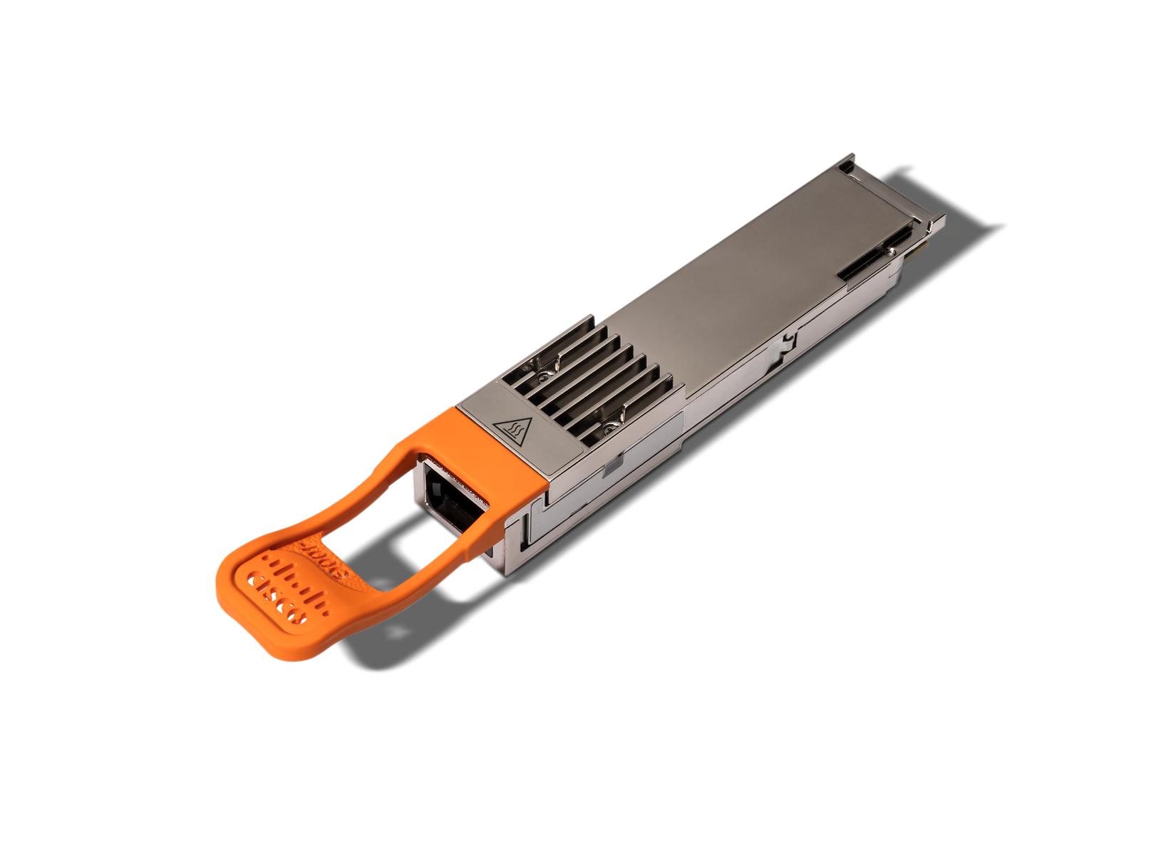
(The OSFP body itself is pictured in section 3.1, and the DR8P module beside its mating MPO-16/APC cable in section 10.2.)
| Module body | Physical clue | Front interface is not implied |
|---|---|---|
| QSFP family | Narrower body; QSFP-DD adds a second row of host contacts | Depending on the optic, the front may be duplex LC, one MPO, dual MPO, or another interface |
| OSFP | Wider and deeper body, commonly with an integrated heat sink | OSFP describes the switch-cage interface, not whether the cable side is LC, MPO-12, or MPO-16 |
Cable-side connectors: duplex LC versus MPO
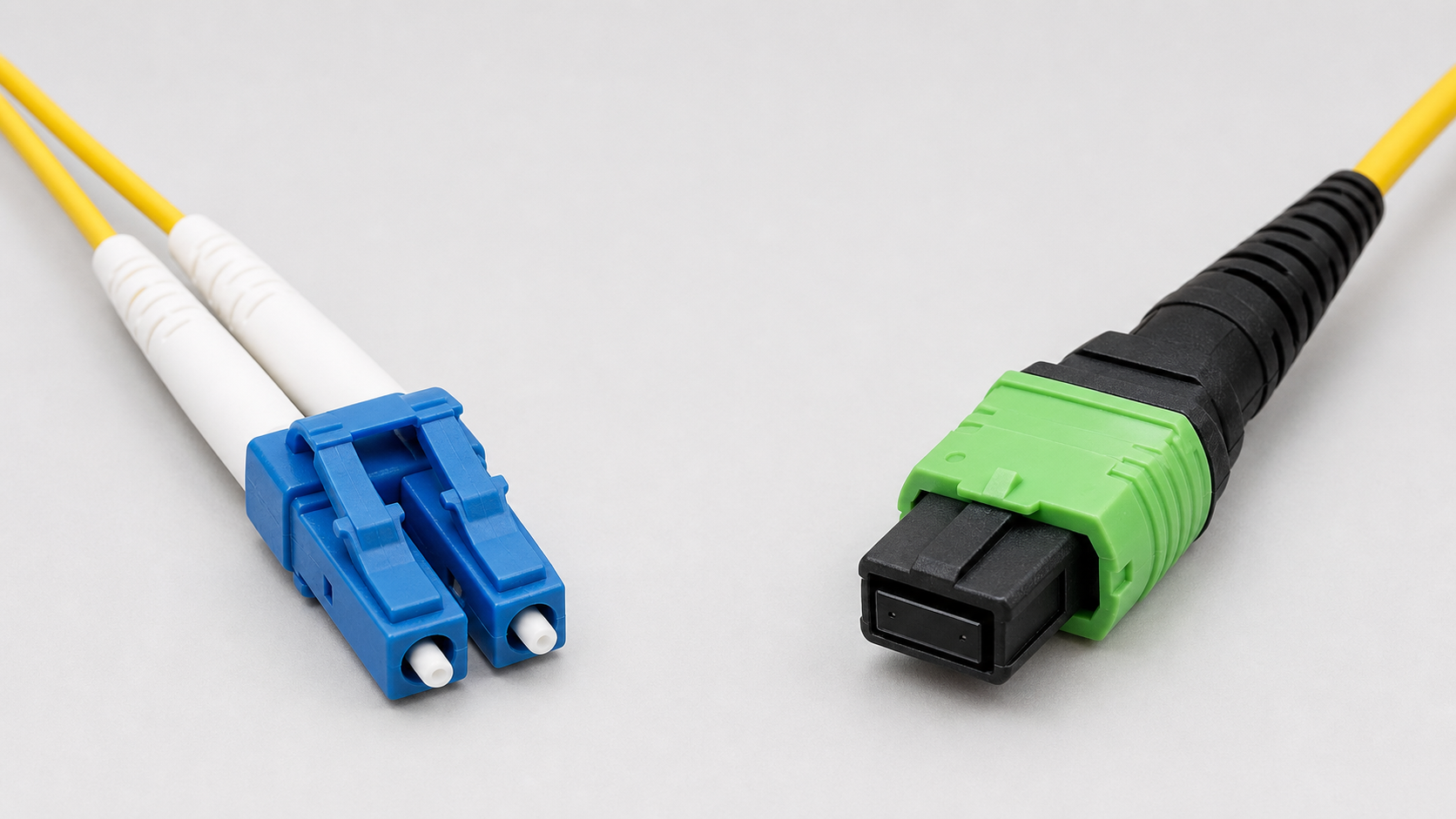
| Photo position | Connector family | Visible clue | Fields that must still be checked |
|---|---|---|---|
| Left | Duplex LC; blue commonly indicates UPC | Two small LC ferrules held together by a duplex clip | UPC/APC polish, Tx/Rx polarity, fiber grade, and module wavelength |
| Right | MPO family; green commonly indicates APC | One wide rectangular multi-fiber ferrule and a keyed housing | MPO-12 versus MPO-16, populated fiber count, pin state, key orientation, polarity, and fiber grade |
Connector color is only a convention; the rendered end faces are not suitable for identifying polish, fiber count, or pin state.
LC carries one fiber per ferrule, and a duplex clip normally keeps the Tx and Rx fibers together. LC is common on FR4/LR4 because four client wavelengths share each transmit and receive fiber. It is also common on coherent ZR/ZR+ modules, which place one tunable line carrier per direction on a duplex single-mode pair. MPO places multiple fibers in one rectangular ferrule and is common on parallel SR4, DR4, VR8, and DR8 optics.
5.2 MPO-8 and MPO-12 can look identical from the outside
“MPO-8” usually means a Base-8 assembly with eight active fibers in the outer positions of a 12-position MPO footprint. A fully populated MPO-12 uses all twelve positions. The outer latch, boot, key, and housing can be the same, so do not identify the fiber count from jacket or connector color alone—check the end face, label, and manufacturer part number.
A real MPO plug up close — and this macro photograph teaches the pin rule better than any diagram: the two steel guide pins flanking the fiber row make this a pinned/male connector, so it must mate with an unpinned/female interface. The row of fiber end faces between the pins is where MPO-8/12/16 population actually differs:
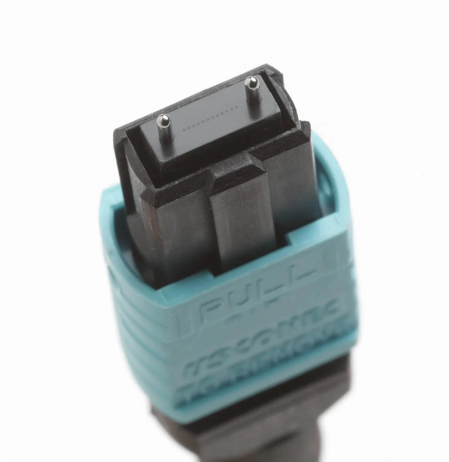
The physical photo identifies the connector family and pin state; the exact diagram below identifies the fiber positions that cannot be trusted from housing shape or color alone.
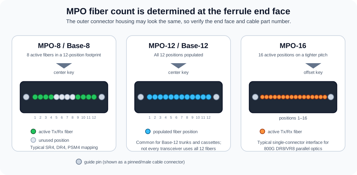
For a typical four-lane parallel optic, positions 1–4 carry one direction and positions 9–12 carry the other; the middle four positions are unused. MPO-16 instead has sixteen positions on a tighter pitch and an offset key, so it does not mate with MPO-12. Some 800G modules avoid MPO-16 by using dual MPO-12, with each connector carrying one eight-fiber group. SENKO’s connector documentation illustrates the center-key MPO-12 versus offset-key MPO-16 distinction.
5.3 Connector selection table
| Connector | Where it appears | Main caution |
|---|---|---|
| Duplex LC | SFP SR/LR, 400G FR4/LR4, coherent ZR | Confirm UPC versus APC and Tx/Rx polarity |
| Simplex LC | BX/BiDi | Both endpoints must use complementary wavelength pairs |
| MPO-12 footprint, eight active fibers (MPO-8/Base-8) | SR4, DR4, PSM4, four-lane parallel breakouts | Confirm which eight positions are populated, plus polarity, key orientation, pins, and APC/UPC |
| MPO-12, twelve active fibers (Base-12) | Trunks, cassettes, and some multiport breakouts | Do not assume a twelve-fiber trunk matches an eight-active-fiber transceiver map |
| MPO-16 | 800G DR8/VR8 | Sixteen active fibers; not interchangeable with MPO-12 |
| Dual MPO-12 | Some 800G DR8/VR8 modules | Two independent eight-fiber groups |
| SC/ST | Legacy panels and industrial environments | Larger connector; adapter loss must enter the link budget |
Ordering check: Blue commonly indicates UPC and green commonly indicates APC, but color is only a clue. Never directly mate APC and UPC end faces. With MPO, also check whether the module is pinned/male and therefore requires an unpinned/female cable connector.
6. Optical reach codes
The suffix is a technology class, not a complete specification. Exact distance depends on Ethernet generation, fiber grade, connector loss, FEC, and vendor implementation.
- SX — hundreds of metres at 1G: one short-wavelength MMF lane; not a DWDM line optic.
- SR — for example, 10G SR at 300 m on OM3 or 400 m on OM4: one or several parallel MMF lanes; not a DWDM line optic.
- VR — about 30–50 m at 400G/800G: very-short-reach parallel PAM4 on MMF; not a DWDM line optic.
- DR — commonly 500 m: parallel 1310 nm single-mode lanes; not a DWDM line optic.
- FR/FR4 — commonly 2 km: direct detect; FR4 multiplexes four O-band CWDM wavelengths; not a DWDM line optic.
- LR/LR4 — 100G commonly 10 km; IEEE 400GBASE-LR4-6 specifies 6 km: direct detect; LR4 multiplexes four O-band LAN-WDM wavelengths; not a DWDM line optic.
- ER — commonly 40 km: a higher-budget direct-detect single-mode optic; not a DWDM line optic.
- ZR — approximately 80–120 km amplified at 400G/800G: one tunable coherent DWDM carrier; designed for a compatible DWDM line system.
- ZR+ — regional to long haul: a coherent carrier with stronger FEC and flexible modulation/rate choices; designed for an engineered DWDM line system.
6.1 LR and LR4
LR means long reach, not line-side DWDM. At 100G and 400G, LR4 is normally a direct-detect Ethernet client optic that multiplexes four closely spaced O-band LAN-WDM wavelengths onto one transmit fiber and receives four wavelengths on the other. Duplex LC and OS2 fiber are typical.
A 100GBASE-LR4 link is commonly specified for 10 km. IEEE 400GBASE-LR4-6 specifies 6 km, while some vendor LR4 modules extend the supported reach to 10 km. LR4 is useful for campus links and unamplified data-center interconnects, but its O-band wavelengths are not ordinary tunable C-band DWDM channels.
6.2 FR and FR4
FR is the shorter, lower-budget relative of LR. A 400GBASE-FR4 module multiplexes four 100G PAM4 wavelengths onto duplex OS2 fiber for up to 2 km. This reduces fiber count compared with DR4, but it creates one 400G optical interface rather than four independently routable 100G interfaces.
FR4 also is not a DWDM line optic. Its internal CWDM wavelengths are combined and separated inside the transceiver; a C-band DWDM mux or ROADM cannot treat those four wavelengths as four line-system channels.
6.3 ZR
Modern 400ZR and 800ZR are coherent line optics. Instead of four direct-detect client wavelengths, the module creates one tunable carrier on the ITU-T DWDM frequency grid and encodes data in amplitude, phase, and polarization. OIF 400ZR targets interoperable point-to-point DCI, while OIF 800ZR targets amplified 80–120 km DCI.
ZR modules commonly use duplex LC/UPC and can connect from a router or switch directly to a compatible passive mux/demux, ROADM, or open line system. The optical design must still satisfy frequency-slot, launch-power, filtering, OSNR, amplification, and receiver-power requirements.
6.4 ZR+
ZR+ is not simply “ZR with more transmit power.” OpenZR+ adds stronger oFEC, multi-rate 100/200/300/400G operation, and modulation choices such as QPSK, 8QAM, and 16QAM. Lower-order modulation trades capacity for reach; the actual distance depends on the module mode and complete line system.
OpenZR+ targets regional and long-haul DCI and carrier applications, including multi-span amplified links and ROADM infrastructure. ZR+ interoperability applies only to supported modes; host software, CMIS application codes, FEC, grid spacing, baud rate, and line-system filters must all agree.
Older 1G names such as EX and ZX and older 10G ZR products are not equivalent to modern 400ZR/800ZR coherent specifications.
7. How 400G and 800G lane arithmetic works
Modern high-speed host interfaces use PAM4, which transmits two bits per symbol by using four amplitude levels.
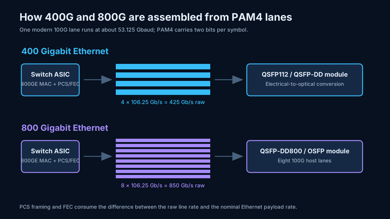
A modern 100G electrical lane operates at roughly:
53.125 gigabaud × 2 bits per PAM4 symbol = 106.25 Gb/s
Therefore:
400G: 4 × 106.25 Gb/s = 425 Gb/s raw
800G: 8 × 106.25 Gb/s = 850 Gb/s raw
PCS framing, alignment markers, and forward error correction consume the difference between the raw line rate and the nominal 400/800 Gb/s Ethernet rate. Earlier 400G QSFP-DD implementations commonly use eight approximately 50G electrical lanes instead of four 100G lanes.
The transmit path is conceptually:
Ethernet MAC
  → PCS encoding and FEC
  → electrical PAM4 SerDes lanes
  → module CDR / retimer / gearbox / DSP
  → laser drivers and modulators
  → optical fibers or wavelengths
The receiver reverses that process. Most high-speed PAM4 links depend on FEC; receiving light is not enough. Incorrect FEC can produce a link that remains down or shows an unusably high bit-error rate.
8. Three optical organizations
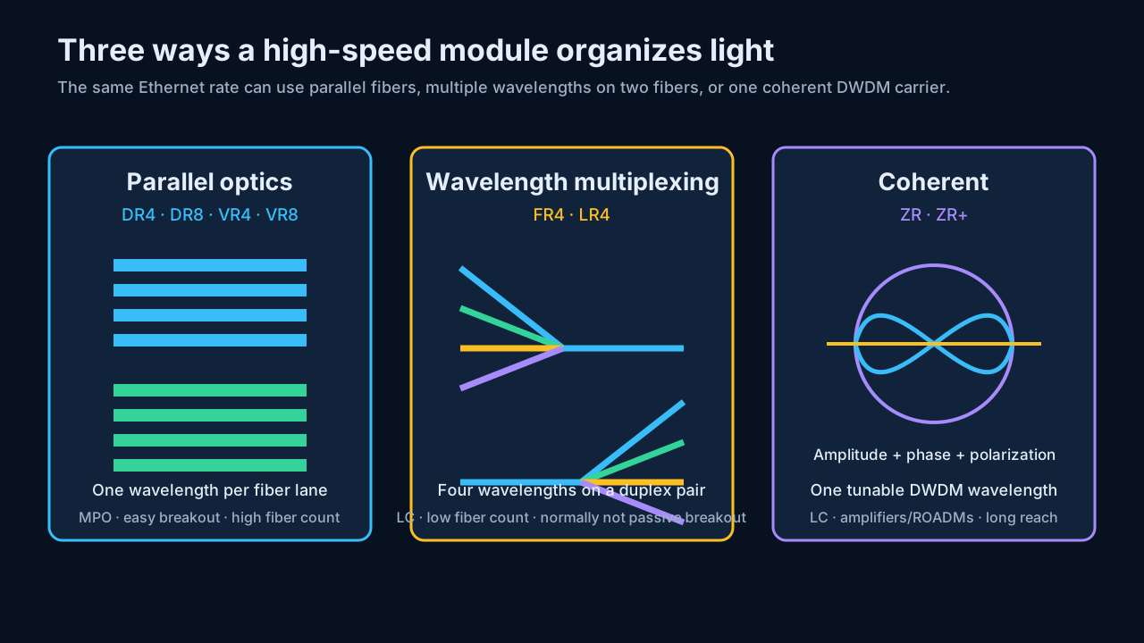
8.1 Parallel optics: VR4, DR4, VR8 and DR8
Every lane has a separate transmit and receive fiber.
400G DR4 uses four 100G transmit fibers and four receive fibers—eight active fibers in an MPO-12 connector. 800G DR8 uses eight transmit and eight receive fibers—sixteen active fibers in MPO-16 or dual MPO-12.
Parallel optics consume more fiber but map cleanly to breakout links.
8.2 Wavelength multiplexing: FR4 and LR4
Four differently colored optical carriers are combined onto one transmit fiber and separated from one receive fiber. A 400G FR4 link therefore needs only a duplex-LC pair even though it contains four 100G optical wavelengths.
The trade-off is breakout. A normal 400G FR4 module presents one 400G Ethernet interface; a passive cable cannot turn its four internal wavelengths into four independent 100G ports. Use an explicitly labeled 4X100G, 8X100G, or 2X400G module when independent endpoints are required.
8.3 Coherent optics: ZR and ZR+
Coherent optics encode information in the amplitude, phase, and polarization of one tunable DWDM carrier. The receiver combines the incoming light with a local laser and uses high-speed ADCs and DSP to reconstruct the signal.
The result is much longer reach and compatibility with amplified DWDM networks, at the cost of more power, heat, DSP latency, and optical engineering.
8.4 Which transceivers can connect directly to DWDM equipment?
“Connect directly to DWDM equipment” can describe two different interfaces:
- Client side of an active transponder or muxponder: the transport device terminates an ordinary Ethernet optic and performs optical-electrical-optical conversion. An LR4 or FR4 module may connect here if the client port supports it, but that module is not itself on the DWDM line.
- Line side, passive mux/demux, ROADM, or open line system: the router-facing module must generate the correct ITU-grid DWDM wavelength or coherent frequency slot. This is the direct IP-over-DWDM case.
| Router/switch transceiver | Usual front connector | Direct to passive DWDM mux or ROADM line? | Correct interpretation |
|---|---|---|---|
| Fixed-channel or tunable DWDM SFP/SFP+/SFP28 | Commonly duplex LC/UPC | Yes, when its ITU channel, power, reach, and host support match | Traditional “colored” 1G/10G/25G DWDM wavelength |
| 400ZR/400ZR+ or 800ZR/800ZR+ in QSFP-DD/OSFP | Commonly duplex LC/UPC | Yes, with a compatible mux/ROADM/open line system | Coherent tunable C-band line optic; some products also support L-band |
| 100G CWDM4 and 100G/400G FR4 or LR4 | Duplex LC/UPC | No on the DWDM line | “Gray” direct-detect client optic; LC shape does not make it DWDM |
| SR4, VR4/VR8, DR4/DR8, or PSM4 | MPO | No | Parallel client fibers, not a wavelength-routed line interface |
| DAC or AOC | Captive cable ends | No | Short client interconnect only |
Cisco’s 10G tunable DWDM SFP+ is an example of a classic ITU-channel LC optic. Modern 400G ZR/ZR+ QSFP-DD modules place the coherent DWDM line function directly in a router or switch port. The grid itself is defined by ITU-T G.694.1.
Before connecting a ZR or ZR+ module to a DWDM system, verify:
- The mux/ROADM passband and channel spacing support the module’s baud rate and selected frequency slot.
- Both endpoints use the same line rate, modulation, FEC, and interoperability mode.
- Launch power and receive power fit the line system; “bright” high-power optics and low-power optics are not interchangeable in every design.
- The OSNR, chromatic-dispersion, polarization-mode-dispersion, and nonlinear budgets support the selected mode.
- The host platform supports the module’s power class, cooling, CMIS application, and coherent configuration commands.
9. Representative 400G modules
9.1 DR4 and FR4/LR4 purchasing pairs
The photo is an illustrative physical comparison, not a vendor part-number reference. Confirm the host cage and exact module data sheet before ordering. The rendered MPO end faces are simplified and do not establish active-fiber positions, key orientation, polarity, or pin state; the table describes a common DR4 ordering combination.
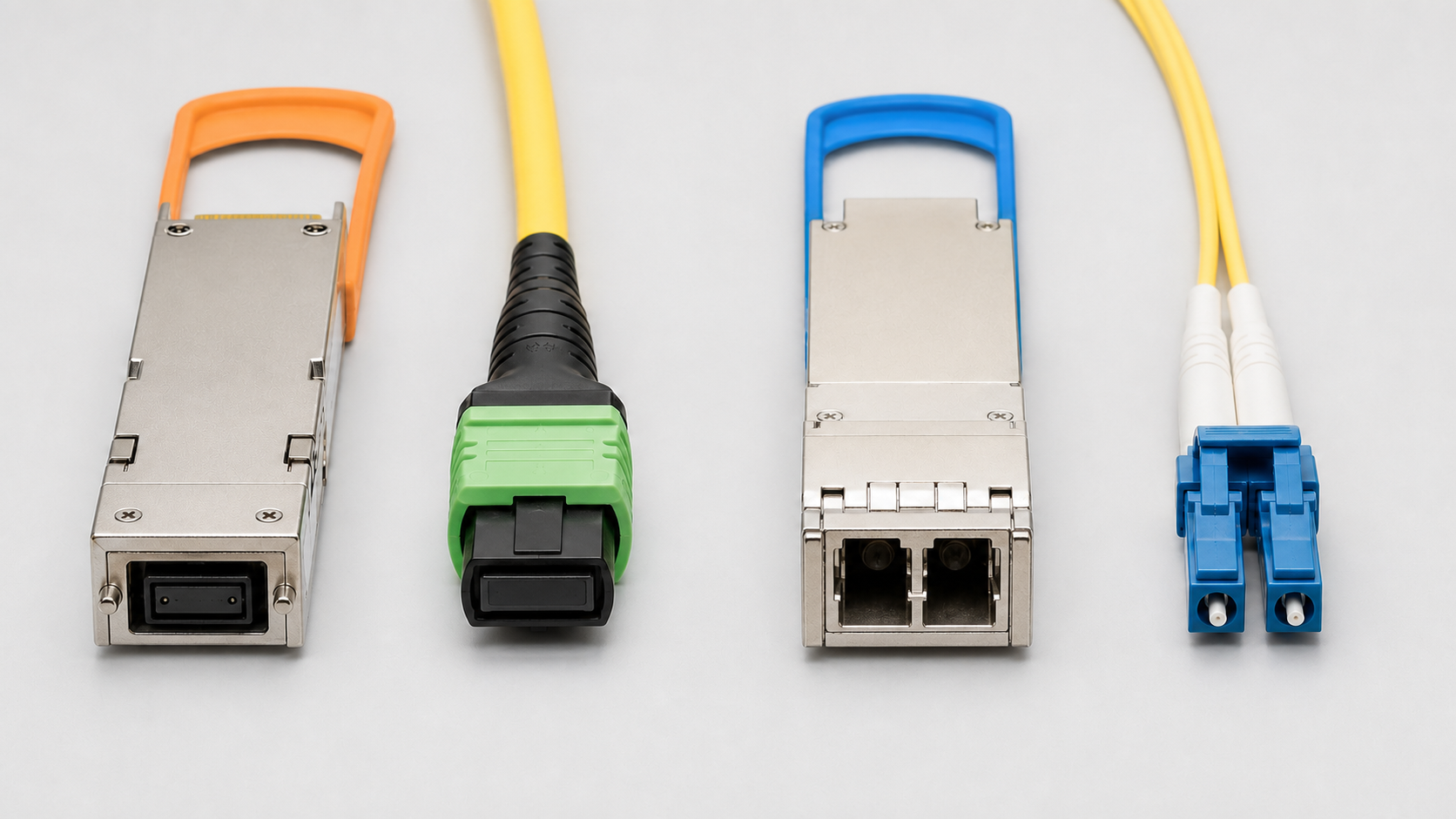
| Specification | 400G DR4 pair, left | 400G FR4/LR4 pair, right |
|---|---|---|
| Typical cable connector | Female/unpinned MPO-12/APC | Duplex LC/UPC |
| Fiber | OS2 single-mode | OS2 single-mode |
| Active physical fibers | Eight: four transmit and four receive | Two: one transmit and one receive |
| Optical organization | Four parallel 100G optical lanes | Four wavelengths multiplexed in each direction |
| Typical reach | 500 m | 2 km for FR4; 6 km for IEEE LR4-6; some vendor LR4 modules reach 10 km |
| Breakout behavior | Often supports 4×100G DR1 or 2×200G DR2 when the host supports it | Normally remains one aggregate 400G optical link |
| Direct DWDM line role | No | No; coherent ZR/ZR+ can look similar but is a different optical class |
Ordering check: Do not order from connector shape alone. Confirm module form factor, reach code, connector polish, MPO pin state and polarity, fiber grade, and host qualification. A duplex-LC front can belong to FR4, LR4, ZR, or ZR+; only the exact module specification establishes DWDM compatibility.
9.2 Reach, breakout, and DWDM roles
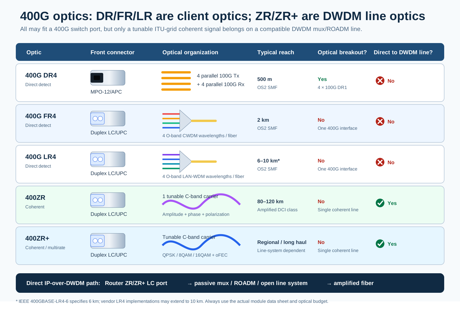
The diagram separates two frequently confused facts: FR4 and LR4 can use duplex LC without being DWDM line optics, while ZR and ZR+ use duplex LC and a tunable coherent ITU-grid carrier that can enter a compatible DWDM line system.
| Model class | Fiber and connector | Reach | How it works |
|---|---|---|---|
QSFP-400G-VR4 | MMF, MPO-12 APC | About 50 m | Four parallel 100G PAM4 lanes for short AI/HPC links |
QSFP-400G-DR4 / QDD-400G-DR4-S | SMF, MPO-12 APC | 500 m | Four parallel 100G lanes; can break out to 4×100G DR1 or 2×200G DR2 |
QSFP-400G-FR4 / QDD-400G-FR4-S | SMF, duplex LC UPC | 2 km | Four CWDM wavelengths multiplexed onto two fibers |
QDD-400G-LR4-S | SMF, duplex LC | 10 km | Four WDM wavelengths for campus/DCI |
QDD-400G-LR8-S | SMF, duplex LC | 10 km | Older eight-wavelength organization |
QDD-4X100G-FR-S | SMF, MPO-12 APC | 2 km | Four independent 100G FR1 interfaces |
QDD-4X100G-LR-S | SMF, MPO-12 APC | 10 km | Four independent 100G LR1 interfaces |
QDD-400G-BD | OM5 MMF, duplex LC | About 100 m | Bidirectional wavelength scheme over an existing duplex pair |
QDD-400G-ZR-S | SMF, duplex LC, DWDM | 80–120 km class | One coherent 400G wavelength |
QDD-400G-ZRP-S / ULH | Amplified DWDM | Line-system dependent | Regional to ultra-long-haul coherent operation |
Cisco’s current 400G QSFP112 data sheet describes VR4, DR4, and FR4 implementations; the broader 400G QSFP-DD portfolio includes SR/VR, DR, FR, LR, BiDi, breakout, DAC, and AOC models.
For coherent transport, 400ZR targets interoperable single-span DCI, while ZR+ and newer ultra-long-haul modules support configurable modulation, channel spacing, and amplified networks. Cisco documents both its 400G ZR/ZR+ modules and a newer 400G ultra-long-haul QSFP-DD.
10. Representative 800G modules
10.1 QSFP-DD800 twin-port FR4 and OSFP DR8
The image is illustrative, not an official vendor photograph. QSFP-DD800 2×FR4 may use dual LC or dual CS depending on the manufacturer, so always check the specific part number. Specifications are based on current QSFP-DD800 2×FR4 documentation and the Cisco OSFP 800G data sheet.
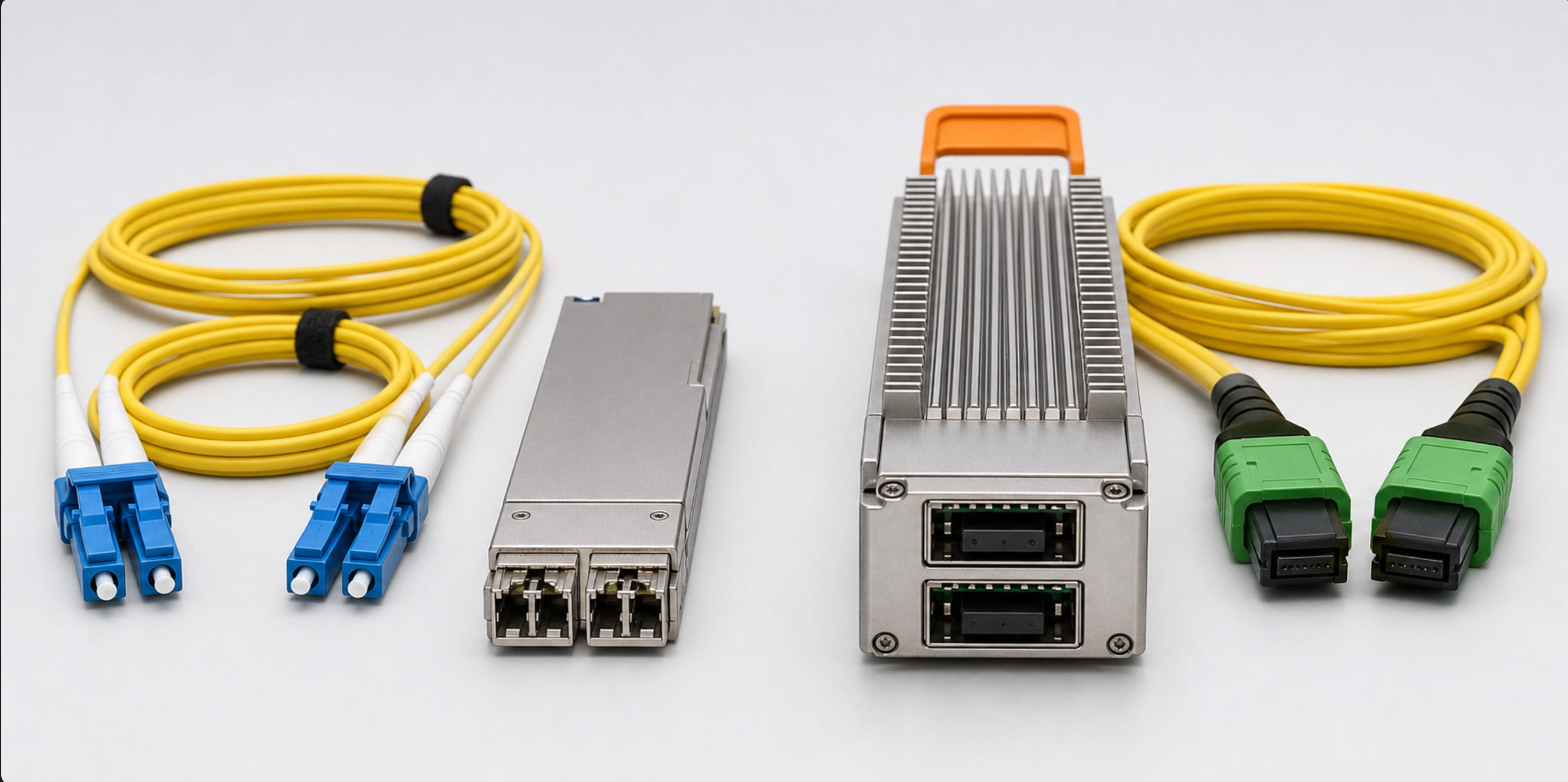
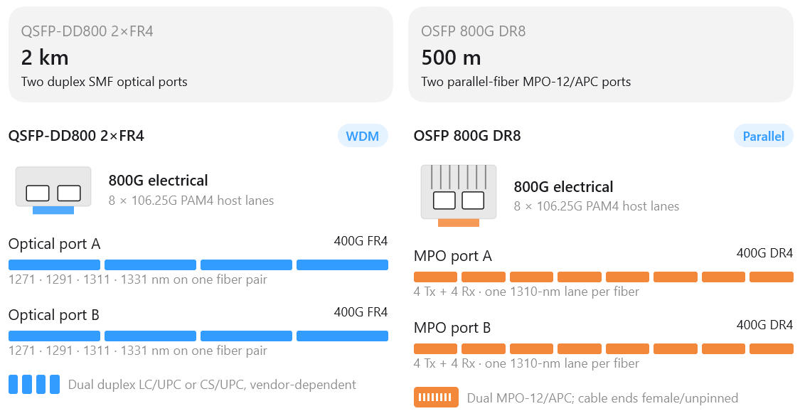
QDD-2X400G-FR4 contains two independent 400G FR4 engines. Each engine multiplexes four 100G wavelengths onto its own duplex-LC pair, giving two 400G links and 800G aggregate electrical capacity.
The real module, for comparison with the rendering above — twin duplex-LC receptacles at the front, the green pull tab labeled with the 2×400G mode, and the QSFP-DD800 signature visible at the rear: a second, deeper row of host contacts carrying the eight electrical lanes:
The two module families solve the same 800G problem in opposite ways — WDM over few fibers versus parallel lanes over many:
| Specification | QSFP-DD800 2×FR4 | OSFP 800G DR8 |
|---|---|---|
| Aggregate rate | 800 Gb/s | 800 Gb/s |
| Independent optical ports | 2 × 400G FR4 | 2 × 400G DR4 |
| Maximum reach | 2 km | 500 m |
| Fiber | OS2 single-mode | OS2 / G.652 single-mode |
| Physical fibers used | 4 total | 16 active total |
| Optical method | 4 CWDM wavelengths per 400G port | 4 parallel Tx/Rx lane pairs per 400G port |
| Cable connector | 2 × duplex LC/UPC or CS/UPC* | 2 × MPO-12/APC female |
| Representative module power | Approximately 16 W* | 14.2 W typical; 16–17 W maximum* |
| Best fit | Longer reach and low fiber count | Short AI-fabric links and native 2×400G breakout |
⚠️ Do not interchange the patch cords: FR4 uses duplex UPC connectors; this DR8 implementation uses parallel MPO-12/APC. Confirm the exact port connector and module qualification from the vendor part number.
* QSFP-DD 2×FR4 connector and power vary by manufacturer. OSFP DR8 values shown follow Cisco’s current module specification.
10.2 OSFP DR8P
OSFP is physically larger and has more thermal headroom. The OSFP-800G-DR8P photographed below uses an MPO-16 APC front for eight transmit and eight receive single-mode lanes — the same eight-lane engine as the DR8 above, delivered through one sixteen-fiber connector instead of two MPO-12s.
The OSFP-800G-DR8P purchasing pair, in detail
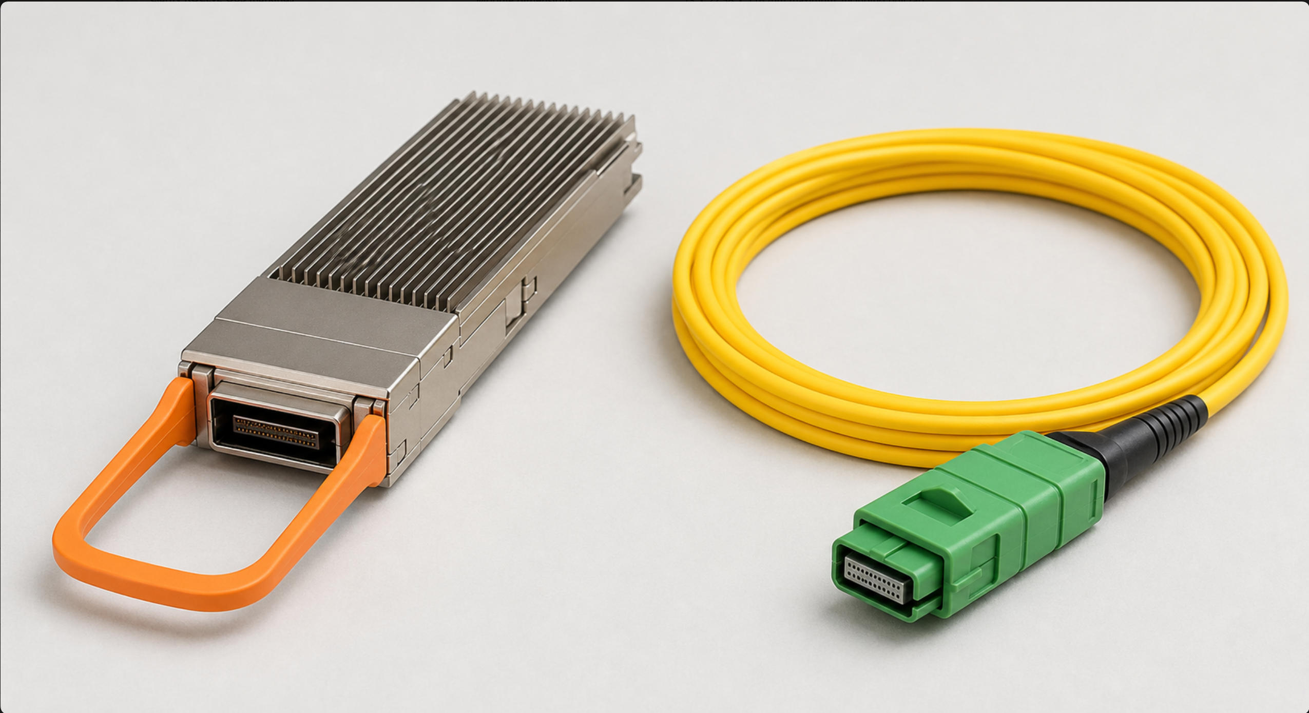
The key purchasing combination is the OSFP-800G-DR8P transceiver + a female/unpinned MPO-16/APC OS2 cable — the pair in the photo: the module’s receptacle is pinned (male), so the cable must be unpinned (female), and the green connector housing is the APC giveaway (section 5 covers both rules). Cisco specifies 800G over eight 100G optical lanes at 1310 nm, up to 500 m — see the official data sheet.
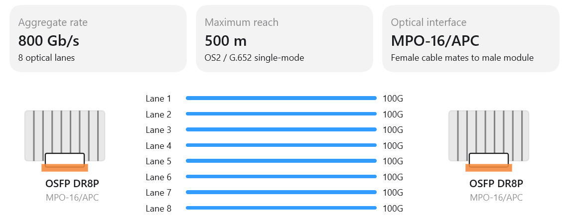
| Specification | Value |
|---|---|
| Ethernet / host interface | 800GE / 800GAUI-8 |
| Optical architecture | 800GBASE-DR8 · 8 parallel Tx/Rx pairs |
| Nominal wavelength | 1310 nm |
| Maximum insertion loss | 3 dB |
| Typical / maximum power | 14.2 W / 16–17 W |
| Module dimensions | 13 × 22.58 × 116 mm maximum, including pull tab |
| Operating temperature | 0–70 °C |
| Required patch cable | OS2 single-mode, MPO-16/APC, female/unpinned |
| Breakout options | 1×800G · 2×400G · 4×200G · 8×100G |
Ordering check: MPO-16/APC, female/unpinned, OS2 single-mode. Confirm polarity and platform breakout support with the switch vendor before ordering — breakout is a system property, not a module property (section 11).
The wider OSFP family for comparison:
| Example model | Fiber and connector | Reach | Organization and breakout |
|---|---|---|---|
OSFP-800G-VR8 | MMF, dual MPO-12 APC | 30 m OM3 / 50 m OM4/5 | Eight parallel lanes; 2×400G, 4×200G, or 8×100G |
OSFP-800G-VR8P | MMF, MPO-16 APC | 30/50 m | Same lane structure using one sixteen-fiber connector |
OSFP-800G-DR8 | SMF, dual MPO-12 APC | 500 m | Eight parallel 100G lanes |
OSFP-800G-DR8P | SMF, MPO-16 APC | 500 m | Eight parallel 100G lanes in one MPO-16 |
OSFP-2X400G-FR4 | SMF, two duplex-LC UPC pairs | 2 km | Two independent 400G FR4 engines |
QDD-8X100G-FR | SMF, dual MPO-12 APC | 2 km | Eight independent 100G FR1 lanes or two 400G groups |
QDD-2X400G-FR4 | SMF, two duplex-LC UPC pairs | 2 km | Two WDM 400G FR4 links |
| 800ZR | SMF, duplex LC, amplified DWDM | Up to about 120 km | One coherent 800G carrier for DCI |
| 800G ZR+ | SMF, duplex LC, amplified DWDM | Over 1,000 km in suitable designs | Coherent metro, regional, and long-haul operation |
Cisco lists typical OSFP client-optic power near 13–14 W and maximum values around 16–17 W for several 800G VR8/DR8 variants. Its QSFP-DD800 FR examples are specified at up to 17 W. These values are implementation-specific, but they explain why port power class, airflow direction, heat sinks, ambient temperature, and adjacent-port population rules must be checked. See the current Cisco OSFP 800G data sheet and QSFP-DD800 data sheet.
OIF defines 800ZR for interoperable amplified 80–120 km DCI links. ZR+ extends the design into metro and regional/long-haul line systems. See the OIF 800G coherent overview and Cisco’s 800G ZR/ZR+ QSFP-DD and OSFP documentation.
11. Breakout is a property of the complete system
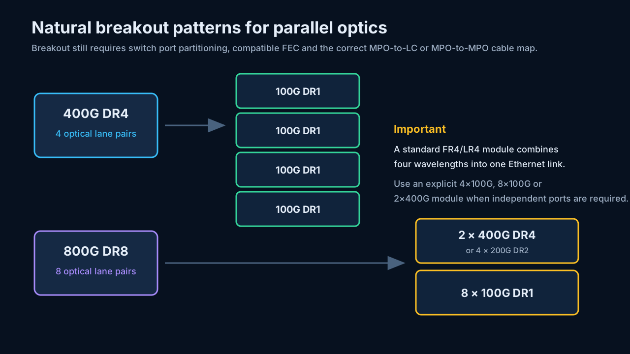
A breakout requires all three layers to cooperate:
- The switch ASIC and operating system must support port partitioning.
- The module must expose independent optical lanes or subports.
- The cable must map the MPO fibers to the correct remote connectors.
Natural examples are:
400G DR4 → 4 × 100G DR1
400G DR4 → 2 × 200G DR2

800G DR8 → 2 × 400G DR4
800G DR8 → 4 × 200G DR2
800G DR8 → 8 × 100G DR1
A twin-port 2X400G-FR4 module is also a breakout device, but the separation occurs inside the module and exits as two duplex-LC interfaces.
12. Optical budget and receiver limits
Distance is shorthand. The real engineering limit is the optical budget:
available loss budget = minimum transmitter power − receiver sensitivity
Path loss must include:
- Fiber attenuation at the operating wavelength
- Connector and adapter loss
- Fusion or mechanical splices
- MPO fan-out and patch-panel loss
- Splitters or passive WDM devices
- Aging, repair, and engineering margin
The received signal must also remain below the receiver’s maximum input power. Long-reach EX/ER/ZX/ZR optics are not automatically better on a short jumper; a high-power transmitter may overload the receiver and require an attenuator.
13. FEC, CMIS, and diagnostics
13.1 Forward error correction
FEC (Forward Error Correction) is math that lets the receiver fix bit errors instead of asking for retransmission. The transmitter appends parity symbols to each block of data; the receiver uses them to detect and correct a bounded number of errors per block. The link deliberately runs “dirty” — a raw PAM4 lane at 50/100G per lane has a native bit-error rate around 10⁻⁴, hopeless by itself — and FEC turns that into a post-correction BER better than 10⁻¹²–10⁻¹⁵. That trade is what makes modern optics affordable: accept a noisy, cheap channel and buy the quality back with coding gain, paying roughly 3–7% bandwidth overhead and some latency.
PAM4 is why FEC stopped being optional: it has three decision boundaries instead of NRZ’s one, so its optical and electrical eye openings are much smaller, making FEC a structural part of every 100G-per-lane design.
The FEC types, in three generations
| FEC | Also called | Where it’s used | Character |
|---|---|---|---|
| Firecode / BASE-R (Clause 74) | FC-FEC, KR-FEC | 10G/25G NRZ era | Weak gain but ultra-low latency (tens of ns); often optional |
| RS(528,514) (Clause 91) | RS-FEC, KR4, CL91 | 100G with 4×25G NRZ lanes (mandatory for SR4; some LR4 links run without) | Reed-Solomon, corrects 7 symbols per codeword, roughly 5 dB coding gain |
| RS(544,514) (Clause 134/119) | KP4 | Everything PAM4: 50G lanes and up — 200G/400G/800G | Corrects 15 symbols per codeword, slightly more overhead than KR4, mandatory; PAM4 does not work without it |
| CFEC | — | 400ZR coherent | Concatenated staircase + Hamming, about 10.8 dB gain, sized for interoperable DCI |
| oFEC | — | OpenZR+/ZR+, OpenROADM coherent | Soft-decision, about 11.6 dB gain — the “stronger FEC” behind ZR+’s extra reach |
Three ideas organize the table:
- Stronger channel impairment → stronger code. NRZ at 25G per lane could get away with weak, optional FEC; PAM4’s squeezed eyes made KP4 non-negotiable; coherent line optics facing 80–120+ km of amplified fiber need the soft-decision heavyweights.
- Hard versus soft decision. The Ethernet FECs are hard-decision: the receiver commits to definite 1s and 0s, then corrects. Soft-decision oFEC instead works from per-bit confidence levels and extracts roughly 1–2 dB more gain — at the cost of DSP power and latency, one reason ZR+ modules run hot.
- KR4 versus KP4 is the classic interoperability killer. Both are Reed-Solomon, both appear as “RS-FEC” in CLIs, and they do not interoperate. One side running CL91 against a side running KP4 — or no FEC — produces exactly the symptom this section exists for: receive power fine, link down or flapping.
Reading the counters
The two numbers that matter operationally are the pre-FEC BER and the corrected/uncorrectable codeword counters. Pre-FEC BER is the margin gauge: KP4 can correct up to roughly 2×10⁻⁴, so a link idling at 10⁻⁶ pre-FEC has enormous headroom, while one at 10⁻⁴ is living on the cliff edge — error-free today, one dirty connector away from uncorrectables. Any nonzero uncorrectable count means frames are genuinely being lost. Corrected codewords climbing steadily is normal operation by design, not a fault — the common misreading is treating corrected counts as errors and “fixing” a healthy link.
When troubleshooting, verify:
- RS-FEC or other FEC mode at both ends — the same named mode, not merely “FEC enabled”
- Pre-FEC BER and corrected-codeword counters
- Uncorrectable codewords
- Lane alignment and deskew
- Whether the optic performs FEC internally or relies on the host
13.2 CMIS management
Modern QSFP-DD and OSFP modules commonly use the Common Management Interface Specification. CMIS lets the host:
- Identify supported applications and lane mappings
- Select 800G, 2×400G, or other operating modes
- Read temperature, voltage, laser bias, and per-lane optical power
- Read thresholds, alarms, and versatile diagnostic monitoring data
- Report module state and firmware revision
- Upgrade module firmware where supported
A module can be mechanically correct and optically compatible yet remain unusable because the host does not support its CMIS application code or power class.
14. Practical selection table
| Requirement | Sensible first candidate |
|---|---|
| Same rack, minimum power and cost | Passive DAC |
| Nearby racks, easier routing | AOC |
| 30–50 m over multimode | VR4 or VR8 |
| Up to 100 m while reusing duplex MMF | Compatible BiDi model |
| Up to 500 m and breakout is important | DR4 or DR8 |
| Up to 2 km on duplex single-mode | FR4 or 2X400G-FR4 |
| Up to 10 km | LR4 |
| Four or eight independent 100G endpoints | Explicit 4X100G or 8X100G optic |
| 80–120 km DCI | ZR with an appropriate amplified design |
| Regional or long haul | ZR+ or ULH coherent optic and engineered DWDM line system |
15. Pre-purchase and troubleshooting checklist
Before ordering or installing a transceiver, verify:
- Cage: SFP, QSFP, QSFP112, QSFP-DD, QSFP-DD800, or OSFP.
- Host rate: Electrical lane count and per-lane baud rate.
- Application: 400GE, 800GE, 2×400GE, or breakout mode.
- FEC: Required mode on both hosts.
- Power and cooling: Maximum module wattage, heat sink, airflow, and port-population restrictions.
- Optical standard: DR4-to-DR4, FR4-to-FR4, or an explicitly supported asymmetric/breakout combination.
- Fiber: OM3/OM4/OM5 or OS2/G.652.
- Connector: LC, MPO-12, MPO-16, or dual MPO-12; APC/UPC; pins and polarity.
- Wavelength: Especially for BiDi, CWDM, DWDM, ZR, and ZR+.
- Loss budget: Include every connector, splice, panel, and margin.
- Platform qualification: Switch model, line card, software version, and vendor coding policy.
- Diagnostics: Tx/Rx power, temperature, voltage, FEC counters, alarms, and lane state.
16. Takeaways
- 400G and 800G are usually not SFP form factors. They are QSFP112, QSFP-DD/QSFP-DD800, or OSFP.
- Appearance is insufficient. Similar housings can carry different speeds, fibers, wavelengths, FEC, and reach.
- DR means parallel and breakout-friendly; FR/LR means low fiber count through client-side WDM; ZR/ZR+ means coherent line-side DWDM. A duplex-LC connector alone does not make an optic DWDM-compatible.
- 400G modern arithmetic is four 100G PAM4 lanes; 800G is eight 100G PAM4 lanes. Earlier 400G QSFP-DD commonly uses eight 50G lanes.
- Breakout is not guaranteed by lane count. It requires a compatible host, module application, FEC mode, and cable map.
- Power and cooling are part of link design at 400G/800G. A module that fits may exceed the port’s thermal envelope.
- The label is only the beginning. Always validate the platform compatibility matrix and the complete optical budget.
Photo credits and reference scope
The SFP-front, DAC/AOC, connector form-factor, 100G purchasing-pair, 400G purchasing-pair, and Section 10 comparison images are illustrative studio renderings created for this article. They are intended for physical recognition, not as dimensionally exact product drawings. Verify dimensions, connector polish, MPO pinning, keying, polarity, active fiber positions, and part number against the manufacturer’s documentation.
The copper RJ45 SFP, Compact BiDi SFP, DAC, AOC, 100G QSFP28 lineup, QSFP112, QSA, QSFP-DD800, and OSFP product photographs are reproduced for identification and technical commentary from the linked Cisco data sheets: 1G SFP, 10G SFP+, 100G QSFP, 400G QSFP112, QSFP-DD800, and OSFP 800G.
The MPO close-up photograph is reproduced for identification and technical commentary from Fluke Networks’ Cleaning and Inspecting MPO/MTP Connectors. The single-mode and multimode patch-cord photograph is by Christophe Finot, licensed CC BY-SA 3.0, via Wikimedia Commons. Product identifiers are examples, not purchasing endorsements; current host support and specifications must be confirmed against the vendor’s compatibility matrix.
