
VXLAN EVPN Architecture
VXLAN EVPN combines a scalable Layer 2 data plane with a standards-based MP-BGP control plane. VXLAN carries Ethernet frames across a routed IP fabric; EVPN distributes endpoint, subnet, and tunnel-reachability information so the fabric does not have to discover everything by flooding.
Contents — 22 sections
Standards and implementation scope
VXLAN EVPN is not defined by one document. The architecture is assembled from a data-plane encapsulation, an EVPN control plane, a mapping between EVPN and network-virtualization overlays, and later IRB and prefix-route extensions:
| Document | Role in the architecture |
|---|---|
| RFC 7348 - VXLAN | VXLAN frame format, VNI, VTEP behavior, UDP transport, MTU, and basic flood-and-learn operation |
| RFC 7432 - EVPN | EVPN NLRI, route types 1-4, multihoming, MAC mobility, split horizon, and designated-forwarder procedures |
| RFC 8365 - EVPN for NVO | Applies EVPN to VXLAN and other IP-overlay encapsulations; defines how VNIs and tunnel attributes are carried |
| RFC 9135 - EVPN IRB | Symmetric and asymmetric integrated routing and bridging procedures |
| RFC 9136 - EVPN IP Prefix | Route Type 5 and overlay-index resolution for IP prefixes |
Cisco configuration examples in this article should be read alongside the current Nexus 9000 VXLAN configuration guide. Platform, line-card, topology, and release restrictions can be more important than the nominal CLI syntax.
1. Why overlays exist
Modern data centers need workload mobility, multi-tenancy, elastic scale, and automation. A traditional Layer 2 design makes the physical network carry too much endpoint state and stretches failure domains as the network grows. An overlay separates two concerns:
- The underlay provides resilient IP reachability between tunnel endpoints.
- The overlay provides tenant-facing Layer 2 or Layer 3 services over those IP paths.
This separation lets the fabric core concentrate on high-capacity IP forwarding. Endpoint state is moved toward the leaf switches, where hosts actually attach. Multiple tenants can share the same physical network while keeping independent address spaces and policies.
1.1 Layer 2 and Layer 3 overlays
A Layer 2 overlay transports complete Ethernet frames. It emulates a LAN segment and therefore supports IP and non-IP payloads, but it also carries the familiar Layer 2 concerns of broadcast, unknown-unicast, and multicast traffic. VXLAN, OTV, and VPLS are examples.
A Layer 3 overlay transports IP packets and abstracts routed connectivity. It gives mobility independently of a single subnet and contains Layer 2 flooding, but it cannot transparently carry arbitrary Ethernet semantics. LISP, IPsec-based overlays, and L3VPNs are examples.
VXLAN is primarily a Layer 2 overlay encapsulation, but VXLAN EVPN fabrics commonly provide both bridging and routing through integrated routing and bridging (IRB).
1.2 Problems VXLAN addresses
Classic VLANs use a 12-bit identifier, giving about 4,000 usable segments. VXLAN uses a 24-bit VXLAN Network Identifier (VNI), providing approximately 16 million segments. The larger space is well suited to large multi-tenant environments.
VXLAN also removes the requirement that Layer 2 adjacency must remain inside one physical switched domain. It encapsulates an Ethernet frame in UDP/IP, allowing the frame to cross routed boundaries and use ECMP paths in the transport network.
2. VXLAN encapsulation and VTEPs
VXLAN is often described as MAC-in-UDP. The original Ethernet frame becomes the payload of an outer UDP/IP packet:
Outer Ethernet
  Outer IP
    UDP (destination port 4789)
      VXLAN header (contains the 24-bit VNI)
        Original Ethernet frame
          Original payload
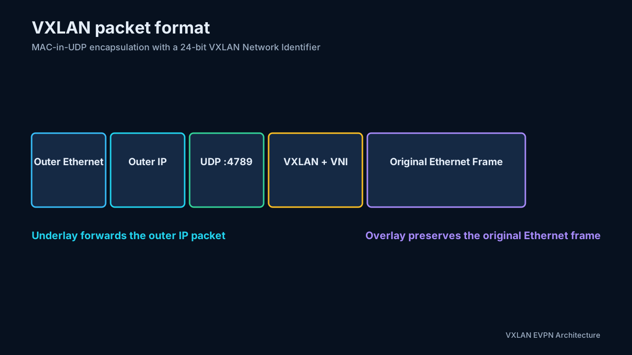
The outer source and destination IP addresses identify the source and destination VTEPs. The inner addresses identify the original communicating endpoints. This distinction is fundamental during troubleshooting: the underlay forwards the outer packet, while the overlay service interprets the inner frame.
2.1 Header fields and encapsulation overhead
The base VXLAN header is eight bytes. Its most important fields are:
- The I flag indicates that the VNI field is valid and must be set for ordinary VXLAN traffic.
- The VNI is 24 bits, providing 16,777,216 possible values before implementation reservations.
- Reserved bits are transmitted as zero and ignored on receipt.
- UDP destination port 4789 is the IANA-assigned default. Early products used other ports, so the destination port can be configurable.
- The UDP source port should be derived from inner-packet fields. This creates flow entropy for ECMP while keeping packets from one flow on a stable path. RFC 7348 recommends the dynamic/private range 49152-65535. RFC 7348, Section 5
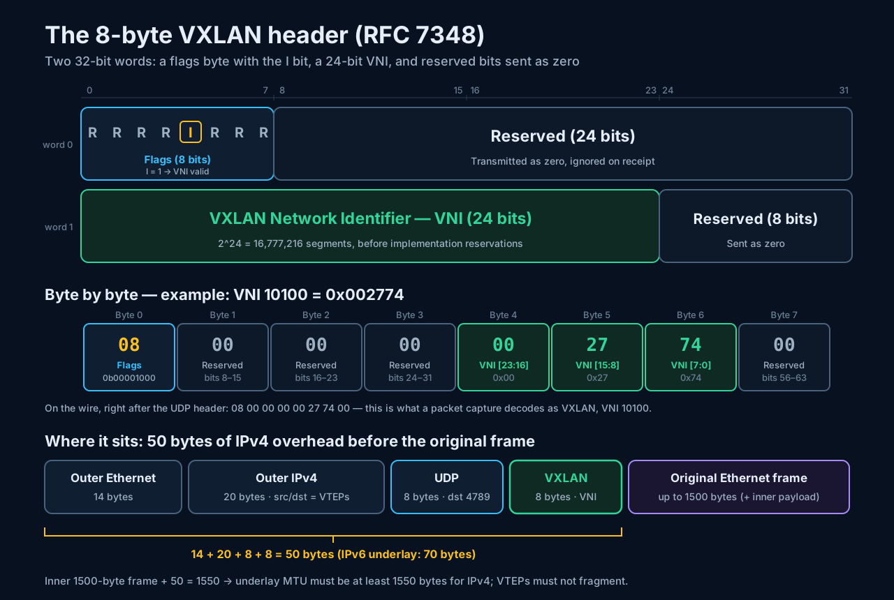
The figure’s byte-by-byte example uses VNI 10100 (0x002774), so the eight header bytes on the wire are 08 00 00 00 00 27 74 00. The first byte is worth reading closely, because it is the one value that never changes in ordinary VXLAN traffic:
bit:    0 1 2 3 4 5 6 7
flag:   R R R R I R R R
value:  0 0 0 0 1 0 0 0   = 0b00001000 = 0x08
The I flag occupies bit 4 (counting from 0 at the left), which carries the weight 2^3 = 8 within the byte. With every reserved bit sent as zero, a valid VXLAN header therefore always starts with 0x08: I = 1, “the VNI field is valid”. A receiving VTEP that sees anything else in this byte must treat the VNI as invalid and drop the packet. This is also why Wireshark displays the VXLAN flags as 0x0800: it decodes the flags byte together with the first reserved byte as a single 16-bit field, and 08 00 is simply the I flag followed by eight zero reserved bits. Bytes 4 through 6 then carry the VNI most-significant byte first (00 27 74 = 10100), and byte 7 is reserved.
For an IPv4 underlay without optional headers, VXLAN adds 50 bytes before the outer FCS: 14 bytes outer Ethernet, 20 bytes IPv4, 8 bytes UDP, and 8 bytes VXLAN. An IPv6 underlay adds 70 bytes before optional extension headers. A fabric transporting a 1500-byte inner Ethernet frame therefore commonly uses a physical MTU of at least 1550 bytes for IPv4, with operational headroom often rounded higher.
VTEPs must not fragment VXLAN packets. Intermediate IPv4 routers technically can fragment them, but a receiving VTEP may discard fragments. The reliable design is an end-to-end underlay MTU that accommodates the complete encapsulated frame and validation with both ordinary and DF-bit test traffic. RFC 7348, Section 4
2.2 Virtual Tunnel End Point
A VTEP (Virtual Tunnel End Point) originates and terminates VXLAN tunnels. A hardware VTEP on a leaf switch has two logical sides:
- A local-facing bridge or routed interface connects servers, hypervisors, firewalls, and other services.
- A fabric-facing IP interface, normally a loopback, identifies the VTEP in the underlay and supplies the outer VXLAN source address.
The same function can run in a hypervisor virtual switch. A physical switch that maps traditional VLANs to VNIs acts as a VXLAN gateway.
2.3 VLAN, bridge domain, and VNI
On a leaf, a local VLAN or bridge domain is mapped to an L2 VNI. The VLAN identifier is locally significant; the VNI is the overlay-wide segment identifier. Although deployments often use an easy-to-read mapping such as VLAN 100 to VNI 10100, the values do not have to be mathematically related.
| Object | Scope | Function |
|---|---|---|
| VLAN/bridge domain | Local to a switch or attachment domain | Connects local interfaces into a Layer 2 segment |
| L2 VNI | Overlay-wide | Identifies a bridged tenant segment across VTEPs |
| VRF | Tenant routing domain | Provides an independent Layer 3 routing table |
| L3 VNI | Overlay-wide, normally one per VRF | Carries routed traffic for symmetric IRB |
3. Underlay design
The underlay must provide IP reachability between every participating VTEP. It can use OSPF, IS-IS, EIGRP, or BGP. All the proven IP-routing practices still apply: redundant links, fast convergence, predictable addressing, and ECMP.
A leaf-spine Clos fabric is common because every leaf is the same number of routed hops from every other leaf. With equal-cost routes through multiple spines, VXLAN flows can be distributed across the fabric. The UDP source port is usually derived from a hash of the inner packet, giving the underlay entropy for ECMP.
Operational requirements include:
- Unique and reachable VTEP loopbacks.
- An MTU large enough for the original frame plus roughly 50 bytes of VXLAN/UDP/IP overhead.
- Consistent routing and ECMP behavior.
- Multicast routing only when underlay multicast replication is selected.
- Failure detection and convergence fast enough for the service objective.
The underlay should know VTEP loopbacks, not tenant prefixes. Tenant reachability belongs to the overlay control plane.
3.1 Underlay routing choices
There is no EVPN requirement to use one particular underlay protocol. Common choices are:
| Underlay | Strengths | Design cautions |
|---|---|---|
| OSPF or IS-IS | Familiar link-state behavior, fast convergence, clear separation from overlay BGP | Requires address and area/level planning; large fabrics need disciplined summarization and flooding scope |
| eBGP | Simple failure domains, natural leaf/spine policy boundaries, strong operational visibility | ASN plan, next-hop handling, multipath, and maximum-path settings must be consistent |
| BGP unnumbered | Minimizes point-to-point IPv4 addressing and works naturally with leaf/spine links | Depends on IPv6 link-local transport and platform support; troubleshooting skills must cover both address families |
Regardless of protocol, verify that every VTEP loopback has equal-cost reachability through the intended spines. A healthy BGP EVPN session does not prove that the data-plane VTEP next hop is reachable at the required MTU.
3.2 ECMP behavior
The outer five-tuple gives the underlay a routable flow key. The outer source and destination IP addresses remain the VTEP pair, so the varying UDP source port supplies most of the per-flow entropy. This normally balances many tenant flows across ECMP paths but keeps one flow ordered. A polarization problem can still occur if platforms use identical hash inputs or if traffic contains too little inner diversity; validate real workload distributions rather than assuming all links will be equal.
3.3 Multicast underlay requirements
When L2 VNIs use multicast replication, the underlay must also provide:
- PIM adjacency on the appropriate routed links.
- Rendezvous-point design for ASM, or a valid SSM design when supported.
- Correct VNI-to-group mapping and acceptable group scale.
- IGMP/MLD and multicast route-state observability.
- Consistent RPF reachability to each VTEP source.
Ingress replication removes these multicast dependencies but transfers replication work and bandwidth to the ingress VTEP. The right choice depends on BUM rate, VTEP count, hardware replication capacity, and operational familiarity—not merely on which configuration is shorter.
4. Design Considerations
4.1 iBGP overlay with an IGP underlay versus eBGP everywhere
The BGP decision occurs at two distinct layers:
- The underlay must advertise or otherwise resolve VTEP loopbacks.
- The overlay uses the
l2vpn evpnaddress family to carry endpoint, VNI-membership, multihoming, and IP-prefix routes.
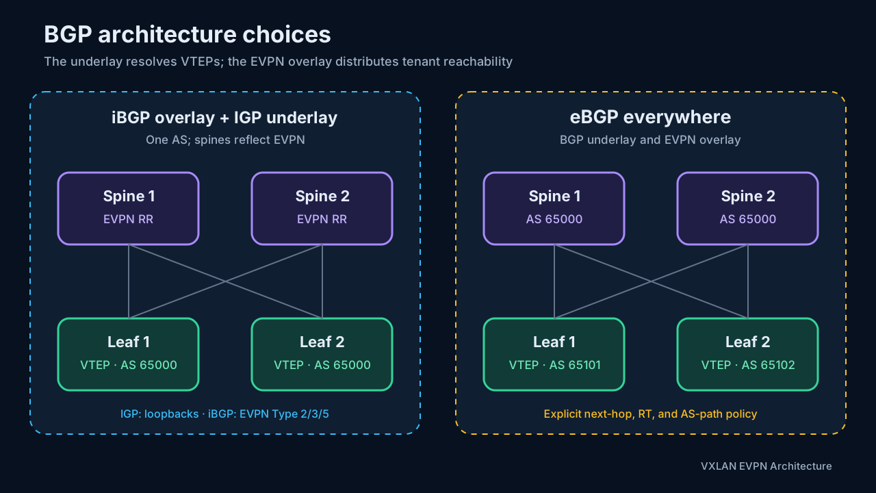
Two widely deployed models are an iBGP EVPN overlay above an OSPF/IS-IS underlay and an “eBGP everywhere” fabric inspired by RFC 7938. RFC 7938 describes eBGP as the stand-alone routing protocol for a large-scale Clos underlay; applying eBGP to the EVPN overlay as well is an implementation design layered on top of that model.
Model A: IGP underlay and iBGP EVPN overlay
OSPF or IS-IS advertises the infrastructure loopbacks. Leaves establish iBGP EVPN sessions with redundant spines or dedicated nodes acting as route reflectors.
This model has several convenient properties:
- iBGP route reflection normally preserves the originating leaf’s BGP next hop, so the EVPN next hop remains the actual VTEP loopback.
- A common fabric ASN makes automatic RT derivation such as
ASN:VNIconsistent on every leaf. - Route reflectors do not need tenant VRFs, SVIs, or VNIs. Their job is to reflect EVPN NLRI and its extended communities.
- The IGP has one narrow responsibility: infrastructure reachability and ECMP to loopbacks.
Its costs are a two-protocol operating model, redundant route-reflector design, and the scaling and flooding characteristics of the selected IGP. The shared ASN also provides less natural hop-by-hop policy separation than an eBGP Clos.
Model B: eBGP everywhere
In this design, BGP IPv4 unicast supplies the underlay and eBGP EVPN sessions supply the overlay. A common ASN scheme assigns one AS to the spine tier and a unique AS per leaf, leaf pair, or rack. It creates clear failure and policy boundaries and removes the need for iBGP route reflection.
The default eBGP behavior requires deliberate overlay policy:
- Preserve the VTEP next hop. When a spine advertises an eBGP EVPN route to another leaf, ordinary eBGP next-hop processing would make the spine the next hop. The overlay route must retain the originating VTEP address. On NX-OS, Cisco documents a route map using
set ip next-hop unchangedon the spine’s outbound EVPN sessions. - Retain EVPN routes without local VNIs. A transit spine has no tenant VRFs or import RTs. On NX-OS,
retain route-target allunderaddress-family l2vpn evpnallows it to retain and advertise EVPN routes that have no locally importable RT. Note that Model A never needs this knob even though its RR spines are equally VNI-less: RFC 4364’s RT-filtering rule is automatically suspended on a route reflector the momentroute-reflector-clientis configured, and it is precisely that exemption that an eBGP transit tier — having no RR role — lacks. Cisco Nexus 9000 eBGP EVPN procedure - Make RTs consistent across leaf ASNs. If automatic RTs are derived as
local-AS:VNI, unique leaf ASNs produce different RTs for the same VNI. Use explicit fabric-wide RTs or a documented feature such as NX-OSrewrite-evpn-rt-asnwhere supported. Cumulus/FRR instead wildcard-matches auto-derived import RTs (*:VNI), so unique-AS eBGP works there without any rewriting — section 7.4 covers both behaviors in detail. - Handle the AS path intentionally. Reusing an ASN across multiple leaves or a redundant leaf pair can trigger eBGP loop prevention. Depending on topology and vendor, designs may require
disable-peer-as-check,allowas-in,as-override, or a different ASN allocation. These commands solve different problems and should not be substituted blindly. - Carry extended communities. EVPN import policy depends on Route Targets, so overlay peers must propagate the required standard and extended communities.
- Multipath for Underlay. By default BGP will select only best path. Manual enablement of BGP multipath maybe required to enable ECMP between leaf-spine.
Sample configuration on spine for nexus:
feature bgp
nv overlay evpn

route-map NEXT-HOP-UNCH permit 10
  set ip next-hop unchanged

router bgp 65000
  router-id 10.255.0.1

  address-family l2vpn evpn
    retain route-target all
    nexthop route-map NEXT-HOP-UNCH

  neighbor 10.0.0.1 remote-as 65101
    address-family ipv4 unicast
    address-family l2vpn evpn
      send-community both
      route-map NEXT-HOP-UNCH out

  neighbor 10.0.0.3 remote-as 65102
    address-family ipv4 unicast
    address-family l2vpn evpn
      send-community both
      route-map NEXT-HOP-UNCH out
ECMP and BGP multipath on NX-OS
An eBGP-everywhere design does not automatically cause every equal path to be installed. On Cisco Nexus, each switch that should forward across multiple eligible eBGP next hops must allow BGP multipath. For physical leaf-to-spine ECMP and redundant reachability to VTEP loopbacks, this is an underlay IPv4-unicast setting:
router bgp 65101
  address-family ipv4 unicast
    maximum-paths 4
Configure it on the leaves so northbound traffic can use all spine uplinks. Configure it on a spine only when that spine can learn the same underlay prefix through multiple leaves and should install those paths. The limit is address-family specific, so an IPv6 underlay requires the corresponding setting under address-family ipv6 unicast.
ASN allocation affects multipath eligibility. If all spines use one ASN, otherwise-equal routes learned through them normally have identical AS paths and maximum-paths is sufficient. If each spine has a unique ASN, the paths have equal length but different AS sequences. NX-OS generally also needs bestpath as-path multipath-relax:
router bgp 65101
  router-id 10.0.0.11
  bestpath as-path multipath-relax

  address-family ipv4 unicast
    maximum-paths 4

  neighbor 10.1.1.0
    remote-as 65001
    address-family ipv4 unicast

  neighbor 10.1.2.0
    remote-as 65002
    address-family ipv4 unicast
multipath-relax relaxes the requirement for identical AS-path contents; it does not make unequal routes equal. The candidate paths must still satisfy the platform’s other multipath rules, including equal AS-path length and compatible local preference, origin, and MED where applicable.
This underlay setting is distinct from multipath under address-family l2vpn evpn. EVPN multipath controls whether multiple eligible overlay paths for the same EVPN NLRI can be retained—for example, when a destination is advertised by multiple VTEPs in an EVPN multihoming design. It does not provide ECMP across the physical spine uplinks. In a conventional fabric, one EVPN route can resolve recursively through several underlay next hops:
EVPN table:      remote MAC/IP -> VTEP 10.255.0.12
Underlay table:  VTEP 10.255.0.12 -> Spine-1
                                  -> Spine-2
Consequently, a fabric that needs both underlay ECMP and overlay-path ECMP may configure multipath in both address families, while a conventional single-originating-VTEP design commonly needs only underlay maximum-paths. Verify both the BGP control-plane choice and the next hops programmed for forwarding:
show bgp ipv4 unicast <prefix>
show forwarding route <prefix>
The first command should show the eligible BGP paths; the second confirms that multiple next hops were installed in hardware.
A representative NX-OS spine pattern is:
route-map NEXT-HOP-UNCH permit 10
  set ip next-hop unchanged

router bgp 65000
  address-family l2vpn evpn
    retain route-target all

  neighbor 10.255.0.11
    remote-as 65101
    update-source loopback0
    ebgp-multihop 2
    address-family l2vpn evpn
      send-community
      send-community extended
      route-map NEXT-HOP-UNCH out
This is a structural example, not a universal template. Whether sessions use directly connected addresses or loopbacks, whether ebgp-multihop is needed, and the exact community/peer-AS commands depend on platform and design.
Operational comparison
| Consideration | IGP + iBGP EVPN | eBGP everywhere |
|---|---|---|
| Protocols | IGP underlay plus BGP overlay | BGP for underlay and overlay |
| Overlay topology | Route-reflected iBGP | Leaf-to-spine eBGP propagation |
| VTEP next hop | Naturally preserved through route reflection | Must be explicitly preserved through transit spines |
| Route Targets | Auto-derived RTs are simple with one ASN | Manual RTs or domain-wide rewrite commonly required |
| Failure domains | Shared IGP and ASN domains | Natural per-session and per-rack AS boundaries |
| Policy | Centralized and relatively minimal | Fine-grained at every eBGP boundary |
| Troubleshooting | Separate IGP and EVPN views | One protocol, but more address families and policy knobs |
| Scaling | Well suited to many enterprise fabrics | Attractive for very large, automation-driven Clos fabrics |
| Main risk | RR/IGP design or hidden dependency | Silent drops caused by next-hop, RT, or AS-path policy |
BGP unnumbered
BGP unnumbered typically uses IPv6 link-local next hops on point-to-point fabric links while advertising IPv4 NLRI. This removes most per-link IPv4 addressing and lets automation derive neighbors from cabling. The current standards reference is RFC 8950, which obsoletes RFC 5549. Platform support, interface discovery, extended-next-hop capability negotiation, and troubleshooting tooling must all be validated before adoption.
Three mechanisms combine to make the address-free fabric link work:
- IPv6 link-local addresses come for free. Every interface with IPv6 enabled derives an
fe80::address from its MAC automatically — that is the address BGP actually peers over, and it needs no planning or IPAM entry. - Neighbor discovery replaces neighbor configuration. The neighbor statement names an interface, not a peer IP (FRR:
neighbor swp1 remote-as external). The router learns the peer’s link-local address and MAC from its IPv6 router advertisements and opens the session tofe80::…%<interface>;remote-as externalaccepts any AS but its own, so every fabric port on every switch can carry an identical configuration line. - IPv4 routes ride the IPv6 session. RFC 8950 extended next-hop encoding lets IPv4 prefixes — the VTEP loopbacks — carry an IPv6 next hop. The route is installed against the interface with an onlink next hop resolved to the peer’s MAC.
The scope limit: unnumbered is a fabric-link pattern, not a fabric-wide one. VTEP loopbacks, host-facing SVIs, and anything reachable beyond one link still need real addresses — which is fine, because loopbacks are all a VXLAN underlay actually has to route.
Platform support is broad enough today that unnumbered no longer restricts vendor choice, though maturity differs:
| Platform | Support | Notes |
|---|---|---|
| Cumulus Linux | Native (FRR) | The reference implementation |
| SONiC | Native (same FRR) | Identical syntax; plan config ownership (config_db vs split mode vs unified FRR management) so config reload does not overwrite it |
| Arista EOS | Yes | Interface eBGP sessions; requires ipv6 enable on fabric links and RFC 8950 next-hop encoding in the IPv4 address family |
| Cisco NX-OS | Yes, recent | RFC 5549 next hops since 9.2(2); full interface peering with link-local auto-discovery only in the 10.x train — the reason classic Nexus designs show numbered /31s or ip unnumbered loopback0 instead |
Mixed-vendor unnumbered fabrics interoperate, since discovery (ND/RA) and the extended next-hop capability (negotiated in the BGP OPEN) are standards. The characteristic mixed-setup failure is one side missing ipv6 enable or not negotiating extended next-hop: the session either never establishes or comes up and installs no IPv4 routes.
For a working end-to-end example with real show bgp summary output — neighbors displayed as hostname(interface) because there is no peer address — see section 3.1 of the Cumulus VXLAN EVPN lab guide.
Practical selection guidance
For an enterprise fabric where operational familiarity, vendor reference designs, and minimal overlay policy matter most, an IGP underlay with iBGP EVPN is often the lower-friction choice. It is particularly attractive when one team already operates OSPF or IS-IS well and the fabric fits comfortably within the vendor’s validated scale.
eBGP everywhere becomes compelling when the organization wants a uniform BGP operating model, explicit per-rack failure domains, strong automation, and a scale at which IGP and route-reflector design become material concerns. Its additional commands are manageable when generated and validated from a source of truth; they are risky when configured manually and inconsistently.
Convergence is not inherently won by either model. It depends on link-failure detection, BFD or equivalent mechanisms where appropriate, route propagation, ECMP programming, hardware behavior, and the number of affected prefixes. Measure failure and restoration under realistic load.
A hybrid eBGP underlay with an iBGP EVPN overlay is valid and is deployed in some designs. It can preserve the familiar iBGP EVPN control plane while using eBGP underlay failure domains, but it also retains two BGP session types and makes overlay session reachability dependent on the eBGP underlay. Choose it only when those trade-offs are intentional and supported by a reference design—not merely as an accidental midpoint.
4.2 BUM Handling
BUM handling spans three parts of the architecture and is mostly orthogonal to whether the EVPN overlay uses iBGP or eBGP:
- EVPN control plane: Type 3 Inclusive Multicast Ethernet Tag (IMET) routes advertise VTEP participation and replication-tunnel information.
- Ingress VTEP: decides whether to make multiple unicast copies or send one packet into an underlay multicast tree.
- Underlay: transports the resulting unicast VXLAN packets or performs multicast-tree replication.
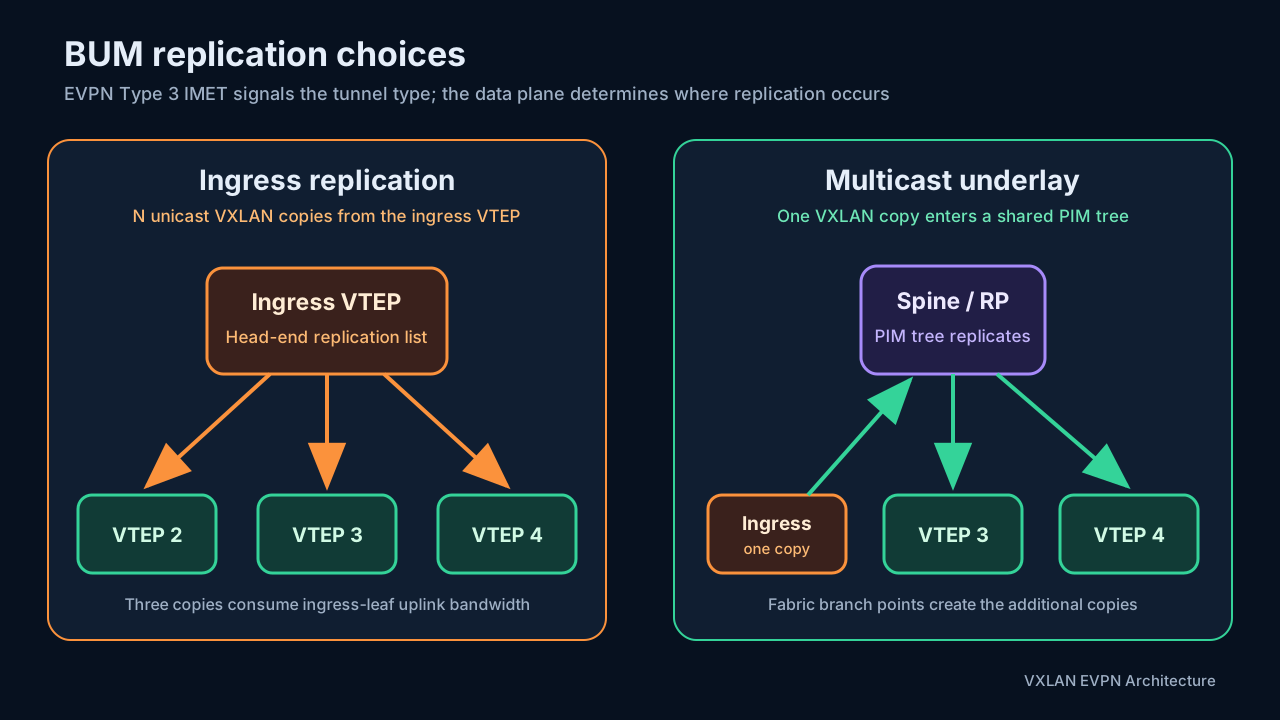
The two primary mechanisms are ingress replication (IR) and multicast underlay. In the standards model, RFC 8365 uses the PMSI Tunnel attribute on the Type 3 route to identify the multicast-tunnel type; defined choices include ingress replication, PIM-SM, PIM-SSM, and BIDIR-PIM. The BGP Encapsulation Extended Community identifies VXLAN as the tunnel encapsulation. Implementations can differ; notably, Cumulus Linux does not advertise a Type 3 route for an L2 VNI whose BUM mode is PIM-SM. RFC 8365, Section 9 NVIDIA EVPN deployment scenarios
Ingress replication
With IR, every VTEP advertising membership in an L2 VNI becomes a candidate remote destination. The ingress VTEP builds a head-end replication list from received Type 3 routes and sends one unicast VXLAN copy to each eligible remote VTEP.
Note — what the Type 3 route actually looks like. This is a real capture from the Cumulus VXLAN EVPN lab guide: leaf1’s EVPN table holding leaf3’s Type 3 (Inclusive Multicast Ethernet Tag) route for VNI 10121, learned over two paths:
*  [3]:[0]:[32]:[10.255.0.13] RD 10.255.0.13:2
                    10.255.0.13 (leaf2)
                                                           0 65102 65000 65103 i
                    RT:65103:10121 ET:8
*> [3]:[0]:[32]:[10.255.0.13] RD 10.255.0.13:2
                    10.255.0.13 (spine)
                                                           0 65000 65103 i
                    RT:65103:10121 ET:8
The
*>path via the spine (65000 65103) is selected as best because its AS path is shorter; the path via leaf2 (65102 65000 65103) is a valid alternate through the MLAG peerlink EVPN adjacency. Decoding the NLRI:[3]:[0]:[32]:[10.255.0.13] │ │ │ │ │ │ │ └── Originating router/VTEP IP │ │ └─────────── IP address length: 32 bits │ └─────────────── Ethernet Tag: 0 └─────────────────── EVPN Route Type 3The route tells the receiving switch that VTEP 10.255.0.13 participates in the L2 VNI identified by
RT:65103:10121— so when the local VTEP receives BUM traffic for that VNI, it knows 10.255.0.13 is one of the remote VTEPs that needs a copy. Type 3 = VTEP/VNI membership and BUM delivery; the flood list is exactly the set of these routes, and a withdrawn route removes its VTEP from the list.ET:8is the Encapsulation Extended Community mentioned above — encapsulation type 8 = VXLAN — telling the receiving EVPN speaker which tunnel encapsulation this route uses.
For a VNI active on 50 VTEPs, a BUM frame arriving on one VTEP can produce up to 49 outgoing VXLAN copies. Replication consumes ingress-leaf bandwidth and hardware replication resources, but the spines maintain only ordinary unicast forwarding state.
IR advantages are:
- No PIM, RP, or multicast group state in the underlay.
- The same IP unicast reachability used by known-unicast VXLAN also transports BUM.
- A natural fit for BGP-only and automation-first fabrics.
- Straightforward failure behavior: a withdrawn Type 3 route removes a destination from the replication list.
IR costs are:
- Replication grows roughly with the number of remote VTEPs in each VNI.
- A BUM-heavy workload can consume substantial bandwidth on the ingress leaf’s uplinks.
- Overlay multicast is replicated as unicast copies unless more specialized multicast features are deployed.
- Replication-list and NVE-peer scale must be included in the hardware capacity budget.
Multicast underlay
With multicast replication, an L2 VNI maps to an underlay multicast group. The ingress VTEP sends one VXLAN packet to that group, and the PIM tree replicates it only where the underlay branches. The VTEPs participating in the VNI join the corresponding tree.
Multicast-underlay advantages are:
- One copy leaves the ingress VTEP regardless of the number of remote VTEPs.
- Replication occurs at efficient branch points in the fabric.
- It scales better for VNIs with many VTEPs and significant BUM or overlay-multicast volume.
Its costs are additional PIM operations, RP design, multicast RPF dependencies, and multicast state on fabric nodes. Troubleshooting now requires correlating the EVPN Type 3 route, VNI-to-group mapping, PIM neighbor state, RPF result, and multicast forwarding tree.
How replication maps to the BGP design choices
An IGP underlay with iBGP EVPN commonly uses multicast replication in classic Nexus validated designs. PIM-SM runs on the routed fabric alongside OSPF or IS-IS; the IGP supplies unicast RPF reachability toward VTEP and RP loopbacks; and redundant spines commonly provide Anycast RP.
An eBGP-everywhere fabric commonly uses ingress replication. This preserves the operational goal of using BGP and unicast forwarding without adding PIM state to the spines. That is a convention, not a protocol requirement: PIM can use routes learned through eBGP for RPF. If multicast is added to a BGP-only underlay, validate the platform’s ECMP RPF behavior, PIM convergence, and vendor-supported topology.
IR itself is independent of the underlay routing protocol. Once the remote Type 3 routes and VTEP next hops are valid, the ingress VTEP sends the same unicast copies whether those loopbacks are reachable through OSPF, IS-IS, iBGP, or eBGP.
Configuring a multicast underlay on NX-OS
The following pattern uses IPv4 PIM Sparse Mode with redundant spine Anycast RPs. It deliberately excludes ingress replication for the listed VNIs.
- Enable PIM sparse mode on every routed fabric link.
- Enable PIM on the relevant loopbacks, including the NVE source loopback where required by the platform design.
- Place redundant RPs in the spine tier.
- Advertise the unique RP and shared Anycast-RP loopbacks through the underlay.
- Configure the same RP group scope on all participating devices.
- Map every L2 VNI to its intended multicast group under
nve1.
NX-OS supports native PIM Anycast RP, which avoids a separate MSDP mesh inside this fabric pattern. Traditional Anycast RP with MSDP is another design, but the two approaches should not be combined accidentally.
Spine example:
feature pim

interface loopback1
  description SHARED-ANYCAST-RP
  ip address 10.0.100.1/32
  ip pim sparse-mode

interface loopback2
  description UNIQUE-RP-ID
  ip address 10.0.1.1/32
  ip pim sparse-mode

ip pim rp-address 10.0.100.1 group-list 239.1.0.0/16
ip pim anycast-rp 10.0.100.1 10.0.1.1
ip pim anycast-rp 10.0.100.1 10.0.1.2
Both spines receive the complete Anycast-RP peer list. 10.0.100.1 is configured identically on each RP, while 10.0.1.1 and 10.0.1.2 are unique addresses identifying the individual spines.
Leaf example:
feature pim

ip pim rp-address 10.0.100.1 group-list 239.1.0.0/16

interface Ethernet1/1
  description TO-SPINE-1
  no switchport
  ip pim sparse-mode

interface Ethernet1/2
  description TO-SPINE-2
  no switchport
  ip pim sparse-mode

interface loopback0
  description NVE-SOURCE
  ip address 10.255.0.11/32
  ip pim sparse-mode

interface nve1
  no shutdown
  source-interface loopback0
  host-reachability protocol bgp

  member vni 30001
    mcast-group 239.1.1.1

  member vni 30002
    mcast-group 239.1.1.2
Current NX-OS also supports global L2 multicast-group configuration with per-VNI overrides on supported releases. Cisco explicitly documents that a multicast group can be configured per L2 VNI and that ingress replication is the alternative. Cisco Nexus 9000 VXLAN Configuration Guide, Release 10.6(x)
Multicast group-allocation strategy
| Strategy | Benefit | Cost |
|---|---|---|
| One group per VNI | Best receiver and failure isolation; VTEPs receive BUM only for that VNI | Highest multicast-group and tree-state consumption |
| One group per tenant or VNI block | Balances group scale with useful scoping | VTEPs may receive traffic for other VNIs sharing the group and discard it after VXLAN lookup |
| One group shared broadly | Minimizes multicast group count | Poor flood scoping and potentially large amounts of unwanted BUM delivery |
The correct allocation depends on the maximum supported multicast groups, number of VTEPs per VNI, expected BUM rate, and hardware replication architecture. Document the mapping rather than generating it implicitly with an undocumented formula.
PIM ASM versus BIDIR-PIM
PIM ASM Sparse Mode with Anycast RP is widely deployed and broadly understood. Each active VTEP source can create source-specific state and may transition toward a shortest-path tree.
BIDIR-PIM maintains one bidirectional shared tree per multicast group and avoids per-source (S,G) state. This can reduce state and SPT-switching churn when every VTEP can be both a source and receiver. On supported Nexus platforms, redundant BIDIR designs commonly use phantom RP rather than the ASM Anycast-RP model. Platform support and group-range configuration must be verified before choosing it. Cisco Nexus VXLAN underlay design guide
How Anycast RP synchronizes source information
Anycast RP gives several physical RPs the same logical RP address. Unicast routing sends a source Designated Router’s PIM Register to its nearest RP, while a receiver’s (*,G) Join can reach a different physical RP. Sharing the address therefore provides reachability and fast failover, but it does not by itself tell every RP which sources are active. The RP set needs a source-synchronization mechanism.
Two mechanisms are commonly encountered:
- Anycast RP with MSDP: the RP that learns a source originates an MSDP Source-Active (SA) message. The other RPs learn the
(S,G)and can join toward the source when they have interested receivers. This is the traditional Anycast-RP design described by RFC 3446. - PIM Anycast-RP (RFC 4610): the RP receiving a Register from a source DR copies that Register to the unique addresses of the other RP-set members. Each receiving RP creates
(S,G)state and can deliver traffic down its own shared tree. A Register received from another configured RP is not copied again, which prevents a replication loop.
RFC 4610 removes the internal MSDP dependency, but it requires native support on every active RP and a consistently configured, deliberately small RP set. MSDP has more protocol machinery and peer state, yet remains necessary on platforms that do not implement RFC 4610 or when source discovery must cross PIM domains. Do not configure both methods between the same internal Anycast-RP members unless the vendor explicitly documents the interaction. RFC 4610 RFC 3446
Why ACI IPN commonly uses BIDIR while generic EVPN often uses ASM
The choice follows multicast-state economics rather than a difference in VXLAN encapsulation.
An ACI Inter-Pod Network can carry many infrastructure multicast groups, with many leaf or spine endpoints acting as both sources and receivers. Under ASM, that pattern can create substantial (S,G) state, Register processing, and shortest-path-tree transitions. BIDIR-PIM keeps traffic on a bidirectional shared tree and maintains (*,G) rather than per-source state in the core. A phantom RP provides a stable RPF vector without requiring the RP address to terminate on one physical router. This makes BIDIR attractive for a dense, many-to-many infrastructure workload.
A general-purpose EVPN fabric often has fewer multicast groups, fewer active VTEP sources per group, or enough multicast-state capacity that ASM’s per-source state is acceptable. ASM with Anycast RP is also supported across a broader range of switching platforms and appears in more vendor reference designs. Consequently, ASM is frequently the conservative interoperability choice, while BIDIR is selected when its state reduction is material and every device in the path supports it.
This is a design tendency, not a protocol rule. Estimate state before selecting the mode:
ASM source state       approximately active_sources_per_group x groups
BIDIR shared-tree state approximately groups
The estimate is intentionally simplified; actual hardware consumption also depends on tree branching, outgoing-interface lists, VRFs, and platform implementation. In particular, do not assume that a Cumulus/FRR-based fabric supports BIDIR merely because RFC 8365 defines a BIDIR-PIM tunnel type—verify the exact software and ASIC release.
Cumulus Linux and NVUE specifics
Cumulus Linux uses PIM-SM plus an MSDP full mesh for redundant Anycast RPs. Current NVIDIA documentation states that Cumulus supports one MSDP mesh group, requires all RPs in the domain to be members, and does not forward a received SA message onward. The resulting full mesh is therefore mandatory rather than optional. NVIDIA Cumulus Linux PIM documentation
The following Cumulus Linux 5.x NVUE sketch uses two RPs. Apply the RP mapping on every PIM router; configure the MSDP mesh only on the RPs. Interface names and some NVUE paths can vary between 5.x releases, so confirm them with nv list-commands and the documentation for the installed release.
RP loopbacks and group mapping:
# On RP1; use a different unique /32 on RP2.
nv set interface lo ip address 10.10.10.101/32
nv set interface lo ip address 10.100.100.100/32

# On every PIM router.
nv set vrf default router pim address-family ipv4 rp 10.100.100.100 group-range 239.1.0.0/16

# Enable PIM on every routed fabric interface that participates in the tree.
nv set interface swp51 router pim
nv set interface swp52 router pim
MSDP mesh on RP1 and RP2:
# RP1
nv set vrf default router pim msdp-mesh-group FABRIC-RPS member-address 10.10.10.102
nv set vrf default router pim msdp-mesh-group FABRIC-RPS source-address 10.10.10.101

# RP2
nv set vrf default router pim msdp-mesh-group FABRIC-RPS member-address 10.10.10.101
nv set vrf default router pim msdp-mesh-group FABRIC-RPS source-address 10.10.10.102

nv config apply
For a global L2VNI-to-group mapping on each VTEP:
nv set nve vxlan flooding multicast-group 239.1.1.1
nv config apply
For per-VNI mappings, NVIDIA documents vxlan-mcastgrp in /etc/network/interfaces:
auto vni30001
iface vni30001
    bridge-access 401
    vxlan-id 30001
    vxlan-mcastgrp 239.1.1.1
    bridge-learning off
    bridge-arp-nd-suppress on

auto vni30002
iface vni30002
    bridge-access 402
    vxlan-id 30002
    vxlan-mcastgrp 239.1.1.2
    bridge-learning off
    bridge-arp-nd-suppress on
After changing /etc/network/interfaces, use ifreload -a during an appropriate change window. NVIDIA notes that one group per L2 VNI gives the best underlay bandwidth isolation, while sharing groups reduces multicast state at the expense of sending some VTEPs traffic for VNIs they do not host. NVIDIA EVPN BUM with PIM-SM
There are three Cumulus-specific caveats worth making explicit:
- No Type 3 advertisement in PIM-SM mode: validate the multicast tree and VNI/group mapping directly; the absence of a Type 3 route for that VNI is expected Cumulus behavior, not automatically a fault.
- Unnumbered BGP: advertise the Anycast-RP address for reachability, but do not use it to form unicast or multicast peerings. Use each RP’s unique address as the MSDP source and, where required, the PIM hello source.
- RP placement in an eBGP Clos: NVIDIA currently recommends not using a spine as RP in this topology. Treat the earlier spine-RP NX-OS example as platform-specific, and follow the Cumulus reference topology when deploying Cumulus with eBGP.
Useful Cumulus checks include:
nv show vrf default router pim
nv show interface swp51 router pim
sudo vtysh -c 'show ip pim neighbor'
sudo vtysh -c 'show ip pim rp-info'
sudo vtysh -c 'show ip msdp peer'
sudo vtysh -c 'show ip msdp sa'
sudo vtysh -c 'show ip mroute'
ip -d link show type vxlan
Verify both the wildcard (*,G) entry and active (S,G) entries, their incoming-interface RPF choice, and their outgoing-interface lists. Then capture on a fabric link and confirm that the outer destination is the configured multicast group and the inner frame belongs to the expected VNI.
Consistency and failure modes
Keep one replication method and a consistent group mapping for a given VNI unless the platform explicitly documents mixed-mode interoperability. A Type 3/PMSI mismatch, inconsistent group, missing PIM join, or failed RPF check can silently blackhole only BUM traffic. The resulting symptom is deceptive: known-unicast traffic may work while ARP, unknown destinations, or overlay multicast fail intermittently.
Validate multicast BUM in this order:
- Confirm the L2 VNI is operational on every intended VTEP.
- Where the implementation uses EVPN IMET signaling for this mode, confirm every VTEP advertises and imports the correct Type 3 route. On Cumulus PIM-SM, its absence is expected.
- Where present, confirm the PMSI tunnel type; in all cases, confirm that the VNI-to-group mapping agrees on every VTEP.
- Confirm PIM neighbors on all routed fabric links.
- Confirm RP reachability and RPF toward each VTEP source.
- Confirm the expected
(*,G)and(S,G)or BIDIR state. - Capture the outer packet and verify source VTEP, destination group, UDP/4789, and VNI.
BUM multicast is not Tenant Routed Multicast
The multicast groups in this section carry Layer 2 BUM for an L2 VNI. Tenant Routed Multicast (TRM) distributes routed customer multicast between subnets and VRFs, using L3 VNIs and additional MVPN-style control-plane procedures. Keep BUM and TRM group ranges, capacity budgets, configuration, and troubleshooting workflows separate.
5. VXLAN data-plane forwarding
Forwarding depends on endpoint location and whether the destination is known.
5.1 Local switching
When source and destination MAC addresses are attached to the same leaf and bridge domain, the frame is switched locally. No VXLAN header is added.
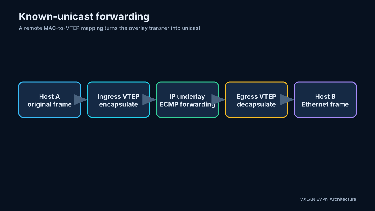
5.2 Known remote unicast
When the destination MAC is known behind another VTEP:
- The ingress leaf learns or receives the mapping between the destination MAC and remote VTEP.
- It maps the local bridge domain to the correct VNI.
- It encapsulates the original frame in VXLAN/UDP/IP.
- The underlay routes the outer IP packet to the remote VTEP.
- The egress VTEP removes the outer headers and sends a normal Ethernet frame to the destination.
5.3 BUM traffic
BUM means broadcast, unknown Layer 2 unicast, and multicast traffic. One ingress frame may need to reach multiple VTEPs. Two common replication models are:
- Underlay multicast: a VNI is associated with an IP multicast group. The ingress VTEP sends one copy, and the multicast-enabled underlay builds the replication tree.
- Ingress replication: the ingress VTEP sends one unicast copy to every interested remote VTEP. This avoids multicast in the underlay but consumes more bandwidth and replication resources as the VTEP count grows.
Traditional flood-and-learn VXLAN is data driven. VTEPs discover remote source MACs from received VXLAN frames. This works, but it makes BUM handling part of endpoint discovery and has several limits:
- Flooding wastes bandwidth and creates large MAC tables.
- Endpoint mobility is harder to converge cleanly.
- A centralized gateway creates traffic hairpinning.
- There is no native control-plane validation of endpoint ownership.
- Troubleshooting depends heavily on observed data-plane behavior.
6. What EVPN adds
EVPN uses the MP-BGP L2VPN EVPN address family as a control plane for the VXLAN overlay. Leaf VTEPs advertise MAC addresses, IP bindings, IP prefixes, and tunnel membership. Remote VTEPs can install forwarding state before data arrives.
Key benefits are:
- Control-plane distribution of Layer 2 MAC and Layer 3 IP reachability.
- Reduced flooding and localized learning.
- ARP/ND suppression.
- Explicit endpoint-mobility signaling.
- Distributed anycast gateways.
- A unicast alternative to multicast for BUM replication.
- Route policies, authentication, and scalable route reflection through BGP.
6.1 Route reflectors
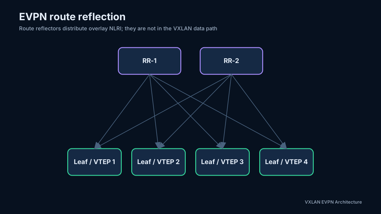
In a small fabric, every leaf could peer with every other leaf. At scale, route reflectors reduce the overlay BGP session count. Leaves advertise EVPN routes to the route reflectors, which reflect them to the other VTEPs. The route reflector does not have to be in the VXLAN data path.
6.2 Underlay versus overlay BGP
If BGP is used in both layers, keep their responsibilities clear:
- Underlay address family: advertises infrastructure links and VTEP loopbacks.
- L2VPN EVPN address family: advertises overlay reachability and membership.
The two control planes can use the same BGP process but carry different NLRI and policies. An EVPN route’s BGP next hop normally resolves through the underlay.
6.3 EVPN address family and route installation
EVPN NLRI uses AFI 25 (L2VPN) and SAFI 70 (EVPN). BGP transports the NLRI plus ordinary path attributes and EVPN-specific extended communities. A received route is useful only when all of the following succeed:
- The BGP path is accepted and selected.
- Its Route Target matches a local MAC-VRF or IP-VRF import policy.
- Its encapsulation is supported, normally VXLAN.
- The VNI and route-type fields are valid for the local service.
- The BGP next hop resolves through the underlay.
- Any required overlay index, such as a gateway IP, MAC, or ESI for a Type 5 route, resolves recursively.
- Hardware resources are available to program the MAC, neighbor, tunnel, and route entries.
This explains a common troubleshooting pattern: a route can appear in show bgp l2vpn evpn yet be absent from the MAC table or tenant VRF. BGP receipt is only one stage of installation.
7. EVPN building blocks: RD, RT, and route types
7.1 Route Distinguisher
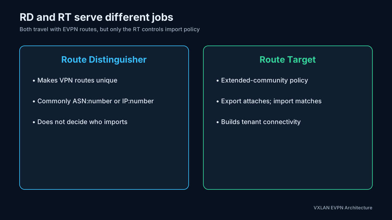
An RD is an 8-byte value prepended to EVPN NLRI to make otherwise identical routes unique. It is not an import/export policy. Two tenants can use the same MAC or IP space and still originate distinct VPN routes because their RDs differ.
Common formats include ASN:number and IP-address:number. Automatic derivation often uses a router ID or VTEP-specific value so different VTEPs originate unique routes.
7.2 Route Target
A Route Target (RT) is an extended community used as policy. An exporting VRF or VNI attaches an RT; an importing VRF or VNI accepts routes carrying the matching RT.
This gives a useful mental model:
- RD answers: How is this route made globally unique?
- RT answers: Which routing or bridging domains should import it?
7.3 Important EVPN route types
RFC 7432 defines EVPN route Types 1 through 4. RFC 9136 later defines the IP Prefix route, Type 5. VXLAN fabrics primarily rely on Types 2, 3, and 5; multihoming additionally uses Types 1 and 4.
| Type | Name | Main VXLAN EVPN purpose |
|---|---|---|
| 1 | Ethernet Auto-Discovery | Multihoming aliasing, mass withdrawal, and Ethernet-segment signaling |
| 2 | MAC/IP Advertisement | Advertises a host MAC and optionally its IP binding |
| 3 | Inclusive Multicast Ethernet Tag | Signals VTEP membership and builds BUM replication lists |
| 4 | Ethernet Segment | Discovers VTEPs attached to the same multihomed Ethernet segment and supports DF election |
| 5 | IP Prefix | Advertises IP prefixes independently of individual host MAC routes |
Type 2: MAC and MAC/IP reachability
A Type 2 route can carry only a MAC or a MAC plus IP address. The route normally includes the RD, Ethernet Segment Identifier when relevant, Ethernet tag, MAC length and address, IP length and address, MPLS-label fields repurposed to carry the VNI, and the advertising VTEP as BGP next hop.
When the IP is present, remote VTEPs can populate both forwarding and neighbor-suppression state. This is one reason control-plane learning reduces ARP flooding.
In a VXLAN encoding, fields named “MPLS Label” by the original EVPN specification carry a 24-bit VNI. Label1 normally identifies the MAC-VRF/L2 VNI. Symmetric IRB can use Label2 to identify the IP-VRF/L3 VNI. RFC 8365 defines the EVPN-to-overlay mapping; treating these fields as literal MPLS labels in a VXLAN packet walk is incorrect. RFC 8365
Type 3: inclusive multicast membership
A Type 3 route tells other VTEPs that the originator participates in a VNI. With ingress replication, the received Type 3 next hops become the head-end replication list. With multicast replication, the route can convey the provider multicast service information associated with the VNI.
Type 5: IP prefix reachability
Type 5 routes carry IP prefixes for a tenant VRF. They are useful for external routes, summarized subnets, border-leaf advertisements, and prefix-based routing that does not need one Type 2 route per endpoint.
Two common models appear in deployments:
- A prefix is advertised with a recursive next hop or router MAC so the remote VTEP routes it through the L3 VNI.
- A subnet is represented through an IRB/SVI context, depending on platform and design.
Type 5 deliberately decouples an IP prefix from a host MAC. It can carry an overlay index—a gateway IP address, router MAC, or ESI—that the receiving NVE resolves recursively to an egress VTEP. If the required overlay index cannot be resolved, the prefix cannot be installed for forwarding even if the Type 5 BGP path itself is valid. RFC 9136, Sections 2-3
7.4 Route targets in practice: auto-derivation, the eBGP wrinkle, and reading RTs in show output
Sections 7.2 and 7.3 introduced RTs and route types separately. This section puts them together: which RT each route type actually carries, how platforms derive RTs automatically, and how to read them on a live switch. The worked example reuses the section 15 tenant so every number lines up with the configuration model there:
Leaf ASN:   65001   (leaf-local — in an eBGP-everywhere fabric each leaf has its own, section 4.1)
L2 VNI:     10100   (VLAN 100, Tenant-1)
L3 VNI:     50111   (Tenant-1 IP-VRF)
VTEP:       10.0.0.11
Host:       192.168.1.10, MAC 0050.5600.0101
Auto-derivation
route-target both auto in section 15.4 — and the equivalent default behavior on Cumulus/FRR with advertise-all-vni — derives RTs by one simple formula:
L2 RT = local ASN : L2 VNI    →  65001:10100
L3 RT = local ASN : L3 VNI    →  65001:50111
The two RTs perform different jobs:
- The L2 RT identifies membership in a bridge domain — the MAC-VRF for VLAN 100 / L2 VNI 10100.
- The L3 RT identifies membership in the tenant IP-VRF — Tenant-1 / L3 VNI 50111.
In symmetric IRB, a single EVPN Type-2 MAC/IP route carries both, which is what lets one advertisement populate the remote MAC table and the remote tenant routing table:
Host 192.168.1.10 (Type-2 MAC/IP)
 ├─ RT 65001:10100  →  belongs to VLAN 100 / L2 VNI 10100 (bridge domain)
 └─ RT 65001:50111  →  belongs to Tenant-1 / L3 VNI 50111 (IP-VRF)
Where the knobs live
On Nexus, the full minimal configuration — features, the VLAN-to-VNI mapping, and the two places where auto-derivation is opted in (the L2 side per EVI, the L3 side per VRF — the same blocks as sections 15.7 and 15.4):
feature nv overlay
feature bgp
nv overlay evpn

vlan 100
  vn-segment 10100

vrf context Tenant-1                ! L3 side (section 15.4)
  vni 50111
  rd auto
  address-family ipv4 unicast
    route-target both auto
    route-target both auto evpn

evpn
  vni 10100 l2                      ! L2 side (section 15.7)
    rd auto
    route-target import auto
    route-target export auto
On Cumulus Linux, the equivalent NVUE configuration is shorter — and notice that no RT appears anywhere in it, because auto-derivation is simply the default:
nv set bridge domain br_default vlan 100 vni 10100
nv set vrf Tenant-1 evpn vni 50111
nv set evpn enable on
nv config apply
(Exact NVUE paths vary slightly by release — some document the enable knob as nv set evpn state enabled; nv config diff before apply shows what your release renders.)
Generally:
| EVPN route | Relevant RT |
|---|---|
| Type 2, MAC-only | L2 RT |
| Type 2, MAC/IP with symmetric IRB | L2 RT and L3 RT |
| Type 3 IMET | L2 RT |
| Type 5 IP prefix | L3 RT (tenant VRF) |
The eBGP wrinkle: auto-derived RTs embed the local ASN
Because the formula embeds the local ASN, an eBGP-everywhere fabric (section 4.1) derives a different RT for the same VNI on every leaf:
Leaf-1 exports:              Leaf-2 exports:
  L2 RT 65001:10100            L2 RT 65002:10100
  L3 RT 65001:50111            L3 RT 65002:50111

Cumulus effectively imports against:
  *:10100
  *:50111
With strict exact-match importing, nobody would import anybody — and this is where the platforms genuinely differ:
- Cumulus/FRR has built-in wildcard import for auto-derived RTs. NVIDIA’s documentation states it directly: for eBGP EVPN peering, “Cumulus Linux treats the import RT as
*:VNI” — the ASN portion is ignored and matching keys on the VNI. Unique-AS eBGP EVPN therefore works with no RT rewriting and no manual RT configuration at all. - The wildcard applies only while the import RT is auto-derived. The moment you configure an import RT manually, matching becomes exact again — a half-manual configuration can quietly break imports that used to work. Some releases accept a wildcard AS portion on a manual import RT (
*:/ANY:forms); verify the syntax on your release before relying on it. - Nexus has no such wildcard. NX-OS needs the RTs to actually match: either configure explicit fabric-wide RTs, or rewrite the ASN portion at the fabric edge with
rewrite-evpn-rt-asnon the eBGP EVPN sessions (the section 4.1 options).
Reading RTs on a live switch
Two habits make RT troubleshooting fast. First, look in the BGP EVPN table, not the ordinary IP routing table — RTs are BGP extended communities and survive only there. Second, expect them only in detailed output; summary views list the routes but usually hide the extended communities. The outputs below are representative and slightly abridged.
Cisco Nexus. The summary view identifies route types but not RTs:
N9K-LEAF1# show bgp l2vpn evpn

Route Distinguisher: 10.0.0.11:32867
*>l[2]:[0]:[0]:[48]:[0050.5600.0101]:[0]:[0.0.0.0]/216
                      10.0.0.11                         100 32768 i
*>l[2]:[0]:[0]:[48]:[0050.5600.0101]:[32]:[192.168.1.10]/272
                      10.0.0.11                         100 32768 i
*>l[3]:[0]:[32]:[10.0.0.11]/88
                      10.0.0.11                         100 32768 i

Route Distinguisher: 10.0.0.11:10
*>l[5]:[0]:[0]:[24]:[10.200.10.0]/224
                      10.0.0.11                         100 32768 i
(The L2 RD 10.0.0.11:32867 is itself auto-derived: VLAN 100 + 32767.) The per-route-type detail is where the RTs appear. Type-2 first — note the two RTs on the MAC/IP route, exactly the symmetric-IRB pattern above:
N9K-LEAF1# show bgp l2vpn evpn route-type 2

Route Distinguisher: 10.0.0.11:32867
BGP routing table entry for
[2]:[0]:[0]:[48]:[0050.5600.0101]:[32]:[192.168.1.10]/272

Paths: (1 available, best #1)
  Path type: local, path is valid, is best path
  10.0.0.11
    Origin IGP, localpref 100, weight 32768
    Extcommunity:
      RT:65001:10100
      RT:65001:50111
      ENCAP:8
      Router MAC:0200.0000.0011
Reading the entry: [2] is the route type, then the host MAC and IP; RT:65001:10100 is bridge-domain membership, RT:65001:50111 is tenant-VRF membership, ENCAP:8 is the BGP encapsulation extended community for VXLAN, and the Router MAC is the router-MAC extended community symmetric IRB uses for the inner Ethernet header (section 10.2).
Type-3 carries only the L2 RT — it signals VNI membership for BUM replication (section 11) — plus the PMSI attribute naming the replication method:
N9K-LEAF1# show bgp l2vpn evpn route-type 3

Route Distinguisher: 10.0.0.11:32867
BGP routing table entry for [3]:[0]:[32]:[10.0.0.11]/88

Paths: (1 available, best #1)
  Path type: local, path is valid, is best path
  10.0.0.11
    Extcommunity:
      RT:65001:10100
      ENCAP:8
    PMSI Tunnel Attribute:
      Tunnel Type: Ingress Replication
      Tunnel Identifier: 10.0.0.11
Type-5 carries only the L3 RT — it is a tenant-VRF prefix, with no bridge domain involved:
N9K-LEAF1# show bgp l2vpn evpn route-type 5

Route Distinguisher: 10.0.0.11:10
BGP routing table entry for [5]:[0]:[0]:[24]:[10.200.10.0]/224

Paths: (1 available, best #1)
  Path type: local, path is valid, is best path
  10.0.0.11
    Origin IGP, localpref 100, weight 32768
    Extcommunity:
      RT:65001:50111
      ENCAP:8
      Router MAC:0200.0000.0011
Cumulus Linux / FRR. Enter the FRR shell with sudo vtysh. The single most useful command — and one Nexus has no direct equivalent of — maps every VNI to its RTs and tenant VRF in one table:
leaf1# show bgp l2vpn evpn vni

Advertise Gateway Macip: Disabled
Advertise SVI Macip: Disabled
Advertise All VNI flag: Enabled
BUM flooding: Head-end replication

VNI       Type  RD                 Import RT       Export RT       Tenant VRF
10100     L2    10.0.0.11:3        65001:10100     65001:10100     Tenant-1
50111     L3    10.0.0.11:5        65001:50111     65001:50111     Tenant-1
A single VNI also has its own detail view — handy for reading the tenant VRF, RTs, and router MAC of the L3 VNI in one shot:
leaf1# show bgp l2vpn evpn vni 50111

VNI: 50111 (known to the kernel)
  Type: L3
  Tenant VRF: Tenant-1
  RD: 10.0.0.11:5
  Router-MAC: 02:00:00:00:00:11
  Import Route Target:
    65001:50111
  Export Route Target:
    65001:50111
The route view shows the same RT pattern as Nexus, with FRR’s more compact rendering (ET:8 is the same VXLAN encapsulation community, Rmac the router MAC):
leaf1# show bgp l2vpn evpn route

Route Distinguisher: 10.0.0.11:3

*> [2]:[0]:[48]:[00:50:56:00:01:01]
                    10.0.0.11                    32768 i
                    ET:8 RT:65001:10100 RT:65001:50111
                    Rmac:02:00:00:00:00:11

*> [2]:[0]:[48]:[00:50:56:00:01:01]:[32]:[192.168.1.10]
                    10.0.0.11                    32768 i
                    ET:8 RT:65001:10100 RT:65001:50111
                    Rmac:02:00:00:00:00:11

*> [3]:[0]:[32]:[10.0.0.11]
                    10.0.0.11                    32768 i
                    ET:8 RT:65001:10100

Route Distinguisher: 10.0.0.11:5

*> [5]:[0]:[24]:[10.200.10.0]
                    10.0.0.11                    32768 i
                    ET:8 RT:65001:50111
                    Rmac:02:00:00:00:00:11
Note the MAC-only Type-2 (first entry) next to its MAC/IP sibling — same MAC, and on this platform both carry the two RTs. Detail for one host, filtered by VNI and MAC:
leaf1# show bgp l2vpn evpn route vni 10100 mac 00:50:56:00:01:01

BGP routing table entry for
[2]:[0]:[48]:[00:50:56:00:01:01]:[32]:[192.168.1.10]

Paths: (1 available, best #1)
  Route [2]:[0]:[48]:[00:50:56:00:01:01]:[32]:[192.168.1.10] VNI 10100
  Local
    10.0.0.11 from 0.0.0.0
      Origin IGP, localpref 100, weight 32768
      Valid, sourced, local, best
      Extended Community:
        RT:65001:10100
        RT:65001:50111
        ET:8
        Rmac:02:00:00:00:00:11
Type-3 and Type-5 have their own filtered views:
leaf1# show bgp l2vpn evpn route type multicast

Route Distinguisher: 10.0.0.11:3
*> [3]:[0]:[32]:[10.0.0.11]
                    10.0.0.11                    32768 i
                    ET:8 RT:65001:10100

leaf1# show bgp l2vpn evpn route type prefix

Route Distinguisher: 10.0.0.11:5
*> [5]:[0]:[24]:[10.200.10.0]
                    10.0.0.11                    32768 i
                    ET:8 RT:65001:50111
                    Rmac:02:00:00:00:00:11
The key pattern
| Route type | Purpose | Typical RTs |
|---|---|---|
| Type 2 | Host MAC/IP advertisement | L2 RT — plus the L3 RT with symmetric IRB |
| Type 3 | VTEP membership / BUM replication | L2 RT |
| Type 5 | Tenant IP-prefix advertisement | L3 RT |
The quickest troubleshooting commands, per platform:
Nexus:                                    Cumulus/FRR:
show bgp l2vpn evpn                       show bgp l2vpn evpn vni
show bgp l2vpn evpn route-type 2          show bgp l2vpn evpn route
show bgp l2vpn evpn route-type 3          show bgp l2vpn evpn route type multicast
show bgp l2vpn evpn route-type 5          show bgp l2vpn evpn route type prefix
The decisive field on both platforms is the extended community RT:<ASN>:<VNI> — read the ASN and VNI out of it, and you know which leaf derived it and which bridge domain or tenant VRF it targets.
The output formats above follow the vendors’ own documentation: NVIDIA Cumulus Linux EVPN inter-subnet routing for the FRR views, and the Cisco Nexus 9000 VXLAN configuration guide for the NX-OS views, including Type-2 routes carrying multiple RTs.
8. EVPN multihoming in detail
EVPN multihoming connects one customer edge, server bond, switch, firewall, or downstream network to two or more VTEPs without relying on a single physical leaf. This is different from MAC mobility: multihoming makes a MAC legitimately reachable through multiple PEs on the same Ethernet segment, whereas mobility means the endpoint moved between different Ethernet segments. RFC 7432, Section 15
8.1 Ethernet Segment Identifier
An Ethernet Segment (ES) is the set of links connecting a multihomed device or network to the participating VTEPs. A nonzero 10-byte Ethernet Segment Identifier (ESI) identifies it. All VTEPs attached to the same ES must derive or configure the same ESI, while unrelated segments must not collide.
Redundancy modes are:
- All-active: all participating VTEPs can forward known unicast traffic to and from the multihomed device. The device commonly sees an LACP bundle.
- Single-active: only one VTEP forwards user traffic for a given service at a time. This is appropriate when the attached device cannot safely receive active-active traffic.
Cisco fabrics may implement dual-homing with vPC, standards-based EVPN ESI multihoming, or platform-specific variants. These are not interchangeable designs: verify support for the selected Nexus model, line card, NX-OS release, and feature combination in the current configuration guide.
8.2 How route types 1 and 4 work together
Type 4 - Ethernet Segment route discovers which VTEPs participate in a nonzero ESI. It carries the ESI and originating router IP and supports DF election and ES-import policy.
Type 1 - Ethernet Auto-Discovery route has two important scopes:
- Per-ES A-D route: represents reachability through a VTEP to the whole Ethernet segment. Withdrawal can invalidate many dependent MAC paths at once, enabling fast or “mass” withdrawal after an access failure.
- Per-EVI A-D route: represents a VTEP’s participation in a particular EVPN instance/VNI on that Ethernet segment. Remote VTEPs use it for aliasing and backup-path behavior.
Together, these routes let remote VTEPs build paths before every individual MAC has been learned through every multihoming VTEP.
For the full control-plane, forwarding, and failure walkthrough, see Appendix A: EVPN Type 1 and Type 4 multihoming reference.
8.3 Aliasing and known-unicast load balancing
Suppose a host MAC is learned and advertised by only one leaf in an all-active pair. A remote VTEP can still infer, from the Type 1 per-EVI routes, that the other leaf reaches the same ESI. Aliasing allows remote known-unicast traffic to use the full set of eligible VTEPs instead of being pinned to the leaf that originated the Type 2 route.
The remote VTEP must combine the Type 2 MAC route with the Type 1 Ethernet A-D state. Losing an A-D route removes that VTEP from the eligible next-hop set without waiting for every MAC route to be withdrawn independently.
8.4 Designated Forwarder election
For BUM traffic sent toward a multihomed Ethernet segment, only the Designated Forwarder should deliver a copy for the relevant Ethernet tag/service. Otherwise, parallel VTEPs could send duplicates to the attached device. RFC 7432 defines DF responsibility at the granularity of an Ethernet segment and Ethernet tag; later DF-election extensions can provide better distribution and convergence, but support is implementation-specific. RFC 7432, Section 8.5
DF election does not mean all-active known unicast becomes single-active. It primarily controls multi-destination delivery and other explicitly defined actions.
8.5 Split horizon
Traffic received from an Ethernet segment must not be sent back to that same segment through another VTEP. EVPN split-horizon signaling identifies the originating ES so the receiving PE can suppress this loop. In an MPLS EVPN network this uses an ESI label; VXLAN implementations map equivalent split-horizon semantics to the overlay behavior described by RFC 8365 and platform mechanisms.
8.6 Failure sequences
An access-link or attached-device failure should produce this sequence:
- The local VTEP removes its Ethernet-segment reachability.
- The corresponding Type 1 route is withdrawn.
- Remote VTEPs remove that VTEP from the aliasing next-hop set.
- Remaining all-active VTEPs continue forwarding, or a new single-active/DF role is selected.
- Individual Type 2 routes converge as necessary without being the only fast-failure signal.
Validate failure behavior independently for local-to-remote known unicast, remote-to-local known unicast, BUM traffic, and routed traffic through the anycast gateway.
8.7 MLAG versus EVPN-MH: why a fabric may show no type-1 or type-4 routes
A common observation in real EVPN tables: types 2, 3, and 5 are everywhere, while types 1 and 4 are completely absent — even though FRR and NX-OS print the NLRI format legend for all five types at the top of every capture. The legend describes what the parser can display, not what the fabric contains.
Type-1 and type-4 routes exist only when an interface is configured with a nonzero ESI — that is, when multihoming is implemented the EVPN-native way described in 8.1–8.6. A fabric that multihomes hosts with MLAG (or vPC) instead solves both multihoming problems outside EVPN, before the fabric ever sees them:
- The duplicate-BUM/DF-election problem is handled by the MLAG bond itself: each frame hashes to one member, and the pair behaves as a single logical switch toward the host — no DF election needed, so no type-4 route.
- The aliasing and mass-withdrawal problems disappear because both members originate every EVPN route with the shared anycast VTEP address as next hop. To every remote VTEP the pair is one VTEP; there is no “two attachment points” state for type-1 routes to describe, and the ESI field in every type-2 route is zero.
The trade-off, in both directions:
| MLAG / vPC | EVPN-MH (ESI-based) | |
|---|---|---|
| Route types on the wire | 2, 3, 5 only | 1, 2, 3, 4, 5 |
| Peer coordination | Dedicated peerlink, shared system MAC, proprietary sync (clagd/vPC) | Control plane only — no peerlink |
| Multihoming scope | Exactly two switches | Two or more VTEPs per segment |
| Vendor interop on the pair | Same vendor (proprietary) | Standards-based (RFC 7432) |
| Failure signaling | Anycast next hop stays valid; underlay reroutes | Type-1 mass withdraw, DF re-election |
One nuance if validating an EVPN-MH fabric: even there, type-4 routes are visible only on the switches sharing the segment — they carry the ES-Import route target, so an uninvolved leaf imports none, by design. Absence of type-4 on a random leaf proves nothing; check a segment member.
For a worked example of the MLAG side — a real EVPN table where every route shows the shared anycast next hop and no type-1/type-4 entries exist — see section 13.4 of the Cumulus VXLAN EVPN lab guide.
9. Endpoint learning, mobility, and ARP suppression
9.1 Local and remote learning
A leaf learns a locally attached host from a data-plane source MAC, ARP/ND, or another authorized local mechanism. It then advertises a Type 2 route. Remote VTEPs install the MAC-to-VTEP mapping and, when present, the IP-to-MAC binding.
9.2 Host mobility
When a host moves from VTEP-1 to VTEP-3, VTEP-3 advertises the host with a higher MAC mobility sequence number. Other VTEPs prefer the newer advertisement and update their forwarding entry. The sequence provides an ordered control-plane signal and avoids waiting for an old MAC-table entry to age out.
The first advertisement does not need a MAC Mobility extended community; its effective sequence is zero. A VTEP that learns the same MAC locally on a different ESI advertises a sequence one greater than the highest received sequence. A receiver prefers the higher sequence; equal sequences on different ESIs use the lower advertising PE IP as the RFC-defined tie-breaker. Static/sticky MACs use the static flag and must not be treated as ordinary moves. RFC 7432, Section 15
Duplicate or rapidly oscillating advertisements should be treated as an operational warning. RFC 7432’s default duplicate-MAC detection example is five moves within 180 seconds, after which the PE alerts the operator and suppresses further route processing for that MAC until corrective action. Vendor defaults and recovery behavior may differ, so verify the live platform rather than relying on these numbers as universal configuration.
9.3 ARP suppression
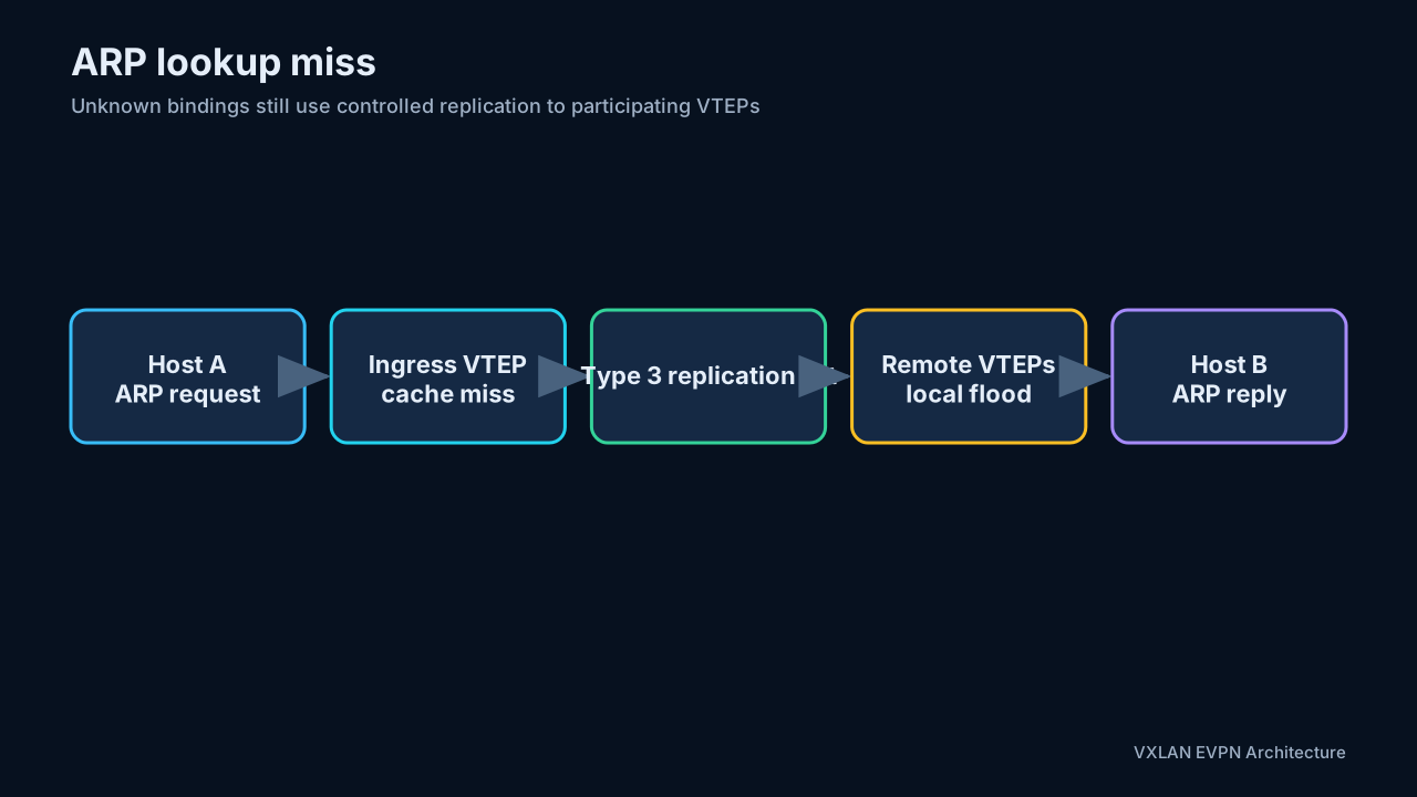
With ARP suppression, an ingress VTEP uses its EVPN-learned IP/MAC database to answer an attached host’s ARP request locally. The request does not need to be flooded across the VNI.
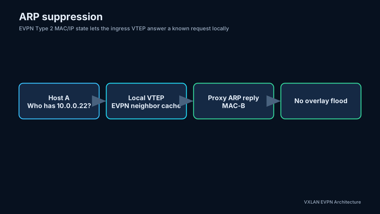
If the lookup misses, the VTEP still replicates the request to the appropriate remote VTEPs. Suppression reduces known-neighbor broadcasts; it does not eliminate the need for a valid BUM mechanism.
IPv6 uses the analogous Neighbor Discovery suppression behavior when supported.
ARP and ND suppression are hardware- and release-dependent features. On Nexus platforms, the SVI state, anycast-gateway configuration, TCAM allocation, and consistency across VTEPs can affect support. Current NX-OS documentation also lists combinations where ND suppression is unavailable or restricted, including some Multi-Site, vPC, IRB, and firewall scenarios. Always check the exact release and platform matrix before enabling suppression fabric-wide. Cisco Nexus 9000 VXLAN Configuration Guide, Release 10.5(x)
10. Distributed anycast gateway and IRB
A centralized gateway forces traffic to cross the overlay to an aggregation device before it can be routed, then potentially cross back. This adds hops, concentrates state, and creates a scaling and convergence bottleneck.
With a distributed anycast gateway, every participating leaf presents the same default-gateway IP and virtual MAC for a subnet. A workload therefore finds its gateway locally wherever it moves. HSRP or VRRP is not required between all leaves for this function.
10.1 Same-subnet forwarding
Hosts in the same subnet and L2 VNI are bridged. If they are attached to different leaves, the ingress VTEP encapsulates the original Ethernet frame with the L2 VNI.
10.2 Inter-subnet forwarding
Hosts in different subnets require routing. VXLAN EVPN supports two IRB models, and the cleanest way to compare them is to walk the same flow through both. The worked example used throughout this section:
- Host A:
10.1.10.11, VLAN 10, L2 VNI 10010, attached to Leaf 1 - Host B:
10.1.20.22, VLAN 20, L2 VNI 10020, attached to Leaf 2 - Tenant L3 VNI: 50000 — one per tenant VRF, representing the VRF itself rather than any one subnet
- Both leaves present the same distributed anycast gateway, so Host A’s first routed hop is always its local leaf.
Asymmetric IRB
Only the ingress VTEP performs an IP routing lookup. The packet crosses the fabric in the destination subnet’s L2 VNI, and the egress VTEP only bridges the final frame.
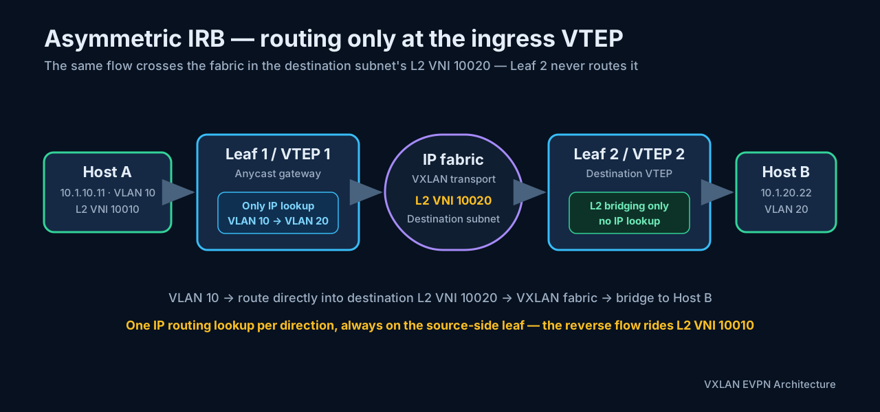
- Host A sends its off-subnet frame to the anycast gateway MAC on Leaf 1.
- Leaf 1 performs the only IP lookup of the path and routes directly from VLAN 10 into the VLAN 20 bridge domain.
- Leaf 1 rewrites the Ethernet header for Host B and encapsulates the frame in destination L2 VNI 10020.
- Leaf 2 decapsulates the frame into VLAN 20. It performs no IP routing lookup for this packet.
- Leaf 2 bridges the frame locally to Host B.
For the reverse flow, Leaf 2 performs the routing lookup and sends the frame to Leaf 1 in L2 VNI 10010. Per RFC 9135, “asymmetric” names the unequal lookup work at the two ends of a single packet’s path — the ingress PE routes and bridges while the egress PE only bridges. A visible consequence is that the routing location changes with traffic direction.
More precisely, RFC 9135 describes three ingress lookups for asymmetric IRB: destination-MAC lookup to the IRB interface, IP-VRF lookup, then destination-MAC lookup in the destination bridge table. The egress PE performs one MAC lookup. The ingress VTEP must therefore know the remote host’s IP-to-MAC binding and must instantiate the destination subnet’s bridge table and IRB interface even when that subnet has no local endpoint. RFC 9135, Section 4
The cost is state. Every VTEP that might route between tenant subnets must instantiate all relevant L2 VNIs — in the example, Leaf 1 needs VNI 10020 and Leaf 2 needs VNI 10010 even with no local host in those segments — plus the corresponding IRB interfaces and, per the lookup sequence above, the remote hosts’ IP-to-MAC bindings. This is simple to visualize but wastes forwarding resources and scales poorly as the number of tenant segments grows.
Symmetric IRB
Both the ingress and egress VTEPs perform an IP routing lookup. The packet crosses the fabric in the tenant L3 VNI.
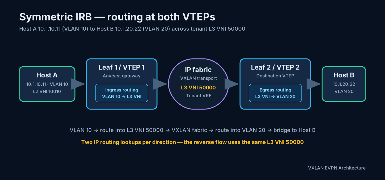
- Host A recognizes that Host B is in another subnet and sends the frame to the anycast gateway MAC.
- Leaf 1 removes the VLAN 10 bridging context and performs an ingress IP lookup in the tenant VRF.
- Leaf 1 encapsulates the packet in tenant L3 VNI 50000 — with Leaf 2’s router MAC as the inner destination MAC — and sends it to Leaf 2.
- Leaf 2 decapsulates the packet and performs an egress IP lookup from the L3 VNI into VLAN 20.
- Leaf 2 rewrites the Ethernet header and bridges the frame locally to Host B.
The reverse flow uses the same two-sided pattern: Leaf 2 routes into L3 VNI 50000, and Leaf 1 routes out of it. “Symmetric” likewise names the lookup pattern at the two ends of one path — the ingress and egress PEs each route and bridge in mirror image — with the practical consequence that the forwarding pipeline is identical in both directions.
The egress leaf needs only its locally used L2 VNIs plus the tenant L3 VNI. This is the more scalable model and the design to default to.
In standards terminology, symmetric IRB forwards between the ingress and egress IP-VRFs. With Ethernet NVO encapsulation such as VXLAN, the inner source and destination MAC addresses are router MACs, not the final destination host MAC. This is why the ingress leaf does not need the remote host’s ARP entry merely to carry routed traffic across the L3 VNI. The egress leaf resolves the local host after its IP-VRF lookup. RFC 9135, Section 4
Side-by-side comparison
| Characteristic | Symmetric IRB | Asymmetric IRB |
|---|---|---|
| IP routing lookups per direction | Two: ingress and egress VTEPs | One: ingress VTEP only |
| VNI on the fabric | Tenant L3 VNI (50000) | Destination subnet’s L2 VNI (10020 or 10010, by direction) |
| Ingress action | Route from the source subnet into the L3 VNI | Route from the source subnet directly into the destination L2 VNI |
| Egress action | Route from the L3 VNI into the destination subnet, then bridge | Decapsulate and bridge only |
| Remote subnets’ L2 VNIs on every VTEP | Not required | Required |
| Remote hosts’ IP-to-MAC bindings at ingress | Not required — inner MACs are router MACs | Required — ingress builds the final Ethernet header |
| TTL / hop limit (RFC 9135) | Decremented at both routing PEs | Decremented at the ingress PE only |
| Scalability | Preferred for many subnets and distributed fabrics | Degrades as subnet count grows |
The TTL row has a practical consequence: packet captures and traceroute interpretation across a symmetric-IRB fabric should account for two routed overlay stages, not one.
BGP EVPN control plane
Both models use BGP EVPN to advertise reachability between VTEPs (section 7.3):
- Route Type 2 — MAC/IP Advertisement: advertises endpoint MAC and optional IP bindings — for symmetric IRB additionally carrying the L3 VNI in the second label field.
- Route Type 3 — Inclusive Multicast Ethernet Tag: supports BUM replication membership for an L2 VNI.
- Route Type 5 — IP Prefix: advertises IP prefixes through an L3 VNI and is commonly associated with scalable symmetric IRB designs.
The underlay provides IP reachability between VTEP loopbacks. EVPN supplies overlay reachability, while VXLAN carries the encapsulated data-plane traffic.
Memory aid — Symmetric: route on both leaves; cross the fabric in the L3 VNI. Asymmetric: route only on the source-side leaf; cross the fabric in the destination L2 VNI.
11. Head-end replication and control-plane suppression
The EVPN control plane minimizes flood-and-learn behavior but does not make every frame unicast. Unknown destinations and genuine broadcasts still require replication.
In head-end replication:
- Each VTEP advertises VNI membership, commonly using a Type 3 route.
- Other VTEPs construct an ingress-replication list for that VNI.
- The ingress VTEP makes one VXLAN unicast copy per remote member.
- Each receiver decapsulates and floods only to the appropriate local interfaces.
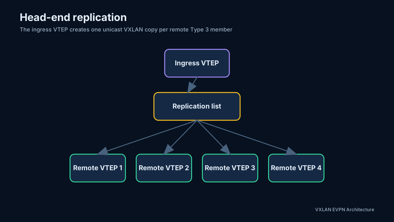
ARP suppression, Type 2 host learning, and Type 3 membership work together: known endpoint resolution remains local or unicast, while unavoidable multi-destination traffic follows a controlled replication list.
12. Design choices: pod, multi-pod, fabric, and site
It is worth carefully distinguishing designs that are often casually grouped together. Each term is really a statement about how far four things are allowed to stretch: the underlay routing domain, the EVPN control-plane domain, the BUM replication domain, and the numbering plan — ASNs, router IDs, VNIs, RDs, and RTs. Pinning those four down is what turns “we have two data centers” into an actual design, so this section works through the ASN assignment, the RD/RT plan, and the interconnect setup for each model.
12.1 Pod
A pod is a repeated leaf-spine building block. A fabric can grow by adding leaves until spine port capacity or scale limits are reached. Adding another group of spines and leaves creates another pod.
One habit makes every later growth step cheaper: allocate identity resources in per-pod blocks from day one — a loopback range per pod, a point-to-point range per pod, an ASN range per pod if eBGP is used. Router IDs stay unique without coordination, rd auto can never collide, and the blocks become natural summarization and filtering boundaries when a second pod — or later a second site — appears.
12.2 Multi-Pod
In a multi-pod design, pods are connected—often through a super-spine layer—but still form one logical fabric:
- One end-to-end overlay domain.
- One end-to-end EVPN control-plane domain.
- One extended underlay reachability domain.
- One BUM replication domain.
- One VNI administrative domain.
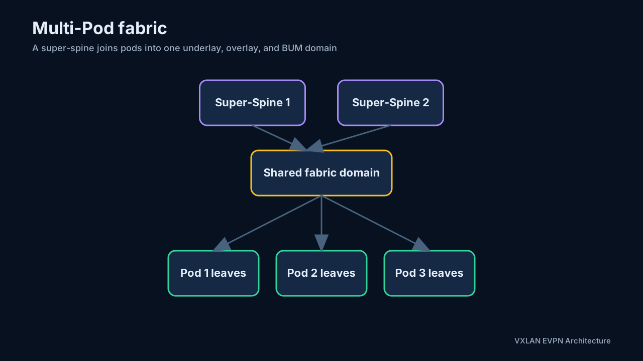
This gives simple end-to-end connectivity, but failure and operational domains grow with the fabric. A route or BUM event can propagate throughout all pods. VTEP-to-VTEP underlay reachability must also extend end to end.
How pods are interconnected
Physically, each pod’s spines uplink to a super-spine tier (two pods can also connect spine-to-spine back to back, but the pattern stops scaling at the third pod). The super-spines carry no tenant state: no VTEPs, no VRFs, no SVIs. Whether they participate in EVPN at all depends on the overlay model below — as iBGP route reflectors they see EVPN NLRI, as eBGP transit they relay it, and in the IP-only interconnect model they never learn it.
Whatever the protocol choice, the pod boundary must satisfy three end-to-end requirements, because a multi-pod fabric is still one fabric:
- Underlay reachability. Every VTEP loopback must remain reachable as a host route from every pod, at the full VXLAN MTU (section 3). Inter-pod links are part of the underlay, so they need the same ~50-byte headroom.
- BUM continuity. With ingress replication, the Type 3 replication list on every VTEP spans all pods, so one broadcast becomes one unicast copy per remote VTEP — and most of those copies cross the inter-pod links. With multicast replication, PIM must run across the inter-pod links, and the RP design should place redundant anycast-RP members in each pod (the section 4.2 pattern) so no pod depends on another for its rendezvous point.
- Control-plane continuity. EVPN routes must travel between pods with their extended communities intact and the originating VTEP preserved as next hop. There is no re-origination at a pod boundary — the boundary is invisible to EVPN.
ASN assignment inside a multi-pod fabric
The section 4.1 decision — iBGP with an IGP, or eBGP everywhere — simply extends one tier upward. Three schemes cover practically all deployments:
One AS end to end, hierarchical route reflection. The whole fabric shares one ASN and one IGP; the overlay is iBGP exactly as in Model A, grown a level: pod spines act as route reflectors for their pod’s leaves, and the super-spines act as route reflectors for the pod spines. Each RR tier and pod keeps its own cluster ID so reflected routes are not rejected between pods:
! Super-spine: top-tier RR; the pod spines are its clients
router bgp 65001
  cluster-id 0.0.0.100
  neighbor 10.0.1.1                  ! Pod-1 spine
    remote-as 65001
    update-source loopback0
    address-family l2vpn evpn
      send-community extended
      route-reflector-client

! Pod-1 spine: RR for its pod's leaves, client of the super-spines
router bgp 65001
  cluster-id 0.0.0.1
  neighbor 10.0.1.11                 ! Pod-1 leaf (client)
    remote-as 65001
    update-source loopback0
    address-family l2vpn evpn
      send-community extended
      route-reflector-client
  neighbor 10.0.0.101                ! Super-spine (non-client)
    remote-as 65001
    update-source loopback0
    address-family l2vpn evpn
      send-community extended
Route reflection preserves the next hop, so leaf-to-leaf tunnels cross pods without any policy. Auto-derived RTs stay consistent because the ASN is the same everywhere.
eBGP everywhere with a transit super-spine AS. The section 4.1 Model B plan gains one tier: each leaf (or rack) keeps its own ASN, each pod’s spine tier gets a pod-scoped ASN, and the super-spine tier gets one transit ASN. A workable allocation from private 2-byte space: super-spines 65000, Pod-1 spines 65010, Pod-2 spines 65020, Pod-1 leaves 65111 upward, Pod-2 leaves 65211 upward. A Pod-2 leaf then receives a Pod-1 host route with:
AS path: 65020 65000 65010 65111
          |     |     |     └ Pod-1 leaf (originator)
          |     |     └ Pod-1 spine tier
          |     └ super-spine transit AS
          └ Pod-2 spine tier
Every transit tier — both pod spines and super-spines — must repeat the full section 4.1 spine checklist: retain route-target all, next-hop unchanged on outbound EVPN sessions, extended communities propagated, and multipath settings on each tier that should spread load. The per-tier ASNs keep ordinary eBGP loop prevention working with no allowas-in gymnastics.
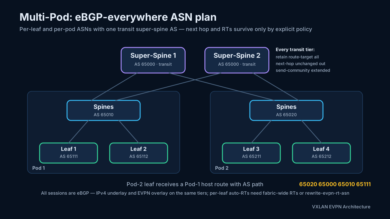
Per-pod AS with an IP-only interconnect. Each pod runs internally as an independent iBGP + RR domain with its own ASN, and the pods exchange EVPN routes over one multihop eBGP EVPN session between the pod route reflectors, configured with next-hop unchanged so tunnels stay leaf-to-leaf. The interconnect routers carry only IPv4 unicast — they advertise the VTEP loopback blocks between pods and never learn EVPN. This is the EVPN adaptation of classic inter-AS option C, and it suits pods separated by an IP WAN that should not participate in the overlay. ipSpace, EVPN Designs: Multi-Pod with IP-Only WAN Routers
| Scheme | Underlay | Overlay sessions | Auto-RT across pods |
|---|---|---|---|
| One AS end to end | One IGP domain spanning pods | iBGP, hierarchical RRs (leaves → pod spines → super-spines) | Consistent automatically |
| eBGP everywhere + transit AS | eBGP hop by hop through the super-spine tier | eBGP EVPN at every tier, next-hop unchanged twice | Broken by design — section 7.4 options required |
| Per-pod AS, IP-only core | Per-pod routing + eBGP IPv4 exchanging VTEP loopbacks | One multihop eBGP EVPN session between pod RRs | Broken at the pod boundary — fabric-wide RTs or rewrite |
iBGP + RR versus eBGP everywhere: considerations and a packet walk
Section 4.1 weighs Model A against Model B inside one pod. Stretching the fabric across pods does not add new trade-offs so much as multiply the existing ones — every consideration now applies once per tier instead of once:
| Consideration | iBGP + RR hierarchy (Model A) | eBGP everywhere (Model B) |
|---|---|---|
| Adding a pod | New pod RRs become clients of the super-spine RRs — a cluster ID and neighbor statements, no new policy | Allocate a spine ASN and leaf ASNs, then apply the full transit checklist to every new session |
| Next hop across pods | Preserved by route reflection; nothing to configure | Preserved only if next-hop-unchanged policy exists at both transit tiers |
| RT consistency | Automatic — one ASN everywhere | Explicit — fabric-wide RTs, rewrite-evpn-rt-asn at each hop, or the FRR wildcard import |
| Where routes silently die | A misconfigured RR hides routes fabric-wide from one point | A missing retain route-target all or next-hop route-map on any one tier |
| Failure and policy boundaries | One AS and usually one IGP: shared fate, minimal policy surface | Per-leaf and per-pod AS boundaries, with a policy hook at every session |
Reading show bgp output | Empty AS path; origin traced via next hop and cluster list | The AS path names the exact leaf, pod, and tier the route crossed |
| Automation dependency | Moderate — RR configuration is small and static | High — identical policy must exist on every session, realistically generated from a source of truth |
Control-plane walk. The same Type-2 route — host 192.168.1.10 behind a Pod-1 leaf whose VTEP is 10.0.1.11 — reaching a Pod-2 leaf.
In Model A (fabric AS 65001, hierarchical RRs):
- The Pod-1 leaf originates the route: next hop
10.0.1.11, RT auto-derived65001:10100. - The Pod-1 spine RRs reflect it to their clients and to the super-spine RRs. Next hop and RT are untouched; the cluster list records the reflection for loop prevention.
- The super-spine RRs reflect it down to the Pod-2 spine RRs — still untouched.
- Pod-2 leaves import on the RT match and install the route with next hop
10.0.1.11.
In Model B (eBGP everywhere, ASNs as above):
- The Pod-1 leaf (AS 65111) advertises to the Pod-1 spines (AS 65010): next hop itself, RT
65111:10100. - The Pod-1 spine is pure transit:
retain route-target allkeeps the route despite no importable RT, the outbound route-map leaves the next hop at10.0.1.11, the AS path grows to65010 65111, and with the rewrite design the RT becomes65010:10100on ingress. - The super-spines (AS 65000) apply the identical treatment.
- The Pod-2 spines (AS 65020) apply it again.
- The Pod-2 leaf (AS 65211) rewrites the RT inbound to
65211:10100— now equal to its own auto-derived import RT — and installs the route with next hop10.0.1.11and AS path65020 65000 65010 65111.
The walkthrough below steps the same route through both models hop by hop. Toggle the model and click through the tiers: amber marks what each hop changes, green marks what it deliberately leaves alone — and the point of the whole comparison is that the green rows are the same in both models, while everything else about the delivery machinery differs, including what breaks and how loudly. The cluster IDs are improvised for the walkthrough (10.0.1.1 / 10.0.0.1 / 10.0.2.1 per tier); the ASNs, RTs, and AS paths are exactly the ones above.
Data-plane walk — identical in both models. Once the route is installed, the models converge completely:
- A host in Pod 2 sends a frame toward
192.168.1.10; its leaf finds the EVPN-installed entry pointing at VTEP10.0.1.11. - The leaf encapsulates once: outer source its own VTEP loopback, outer destination
10.0.1.11, VNI 10100. - The underlay forwards the outer packet leaf → Pod-2 spine → super-spine → Pod-1 spine → Pod-1 leaf, ECMP-hashed per flow on the outer UDP source port at every tier.
- The Pod-1 leaf decapsulates and delivers the original frame.
The interactive walkthrough below generalizes this walk. It uses its own small addressing plan (VTEPs 192.0.2.x, VNIs 1010/1020/50001) rather than the pod plan above, but the mechanics are the point: pick Server A’s destination, toggle between the two section 10.2 IRB models, and watch how the three packet stages change — routed through the VRF’s L3 VNI (symmetric) or straight into the destination VLAN’s L2 VNI (asymmetric), bridged in an L2 VNI, bridged or routed to a second site through either one EVPN domain (a single leaf-to-leaf tunnel, the section 12.2 multi-pod model) or separate domains stitched across three tunnels at border gateways (section 13’s Multi-Site machinery, Arista’s multi-domain EVPN gateway), routed via a leaked route into another VRF’s L3 VNI, or dropped at ingress when no route was imported. The two different-VLAN remote-site cases make an important distinction visible: symmetric IRB uses tenant L3VNI_A 50001, whereas asymmetric IRB uses destination L2VNI_20 1020; merely crossing from VLAN 10 to VLAN 20 does not always put VNI 1020 on the wire. In each multi-domain case, stage 2 expands into three separate packet snapshots — arriving at BGW-A, crossing the DCI, and leaving BGW-B — so the changed outer headers at both tunnel boundaries are explicit. Note what stays constant in every forwarded case: an outer header whose UDP source port carries the ECMP entropy — and a single leaf-to-leaf encapsulation everywhere except the multi-domain cases, whose three-tunnel stitching is exactly the section 14 walk.
The tunnel is one leaf-to-leaf VXLAN encapsulation either way — spines and super-spines route the outer IP packet and never process VXLAN. What differs is the machinery that delivered the route, and therefore the failure modes. In Model A a broken route reflector hides reachability: the route never arrives, and the gap is visible as absence in show bgp l2vpn evpn. In Model B a forgotten next-hop-unchanged policy blackholes it: the spine advertises itself as next hop, attracts VXLAN traffic it has no NVE to decapsulate, and drops it — BGP looks healthy and only the data plane fails. The first design concentrates risk in a few devices; the second spreads a thinner risk across every session.
RD and RT design across pods
Because a multi-pod fabric is one EVPN domain, the RD/RT rules are the single-fabric rules — they just have to hold across a bigger device population:
- RD. Keep
rd autoeverywhere. Auto-derivation builds the RD from the BGP router ID (section 7.4’s10.0.0.11:32867), so the real requirement is that router IDs and VTEP loopbacks are unique across all pods — which the per-pod loopback blocks from section 12.1 guarantee by construction. Unique per-VTEP RDs also keep every VTEP’s path visible through the route reflectors, which multihoming and anycast-gateway advertisements rely on. - RT. With one fabric-wide ASN, auto-derived
ASN:VNIvalues match everywhere and nothing needs configuring. With per-leaf or per-pod ASNs, the section 7.4 wrinkle applies at every AS boundary: either configure explicit fabric-wide RTs per VNI, enablerewrite-evpn-rt-asnon each eBGP EVPN session (NX-OS), or rely on the*:VNIwildcard import that Cumulus/FRR applies to auto-derived RTs. - VNI. The VNI space is fabric-global. One allocation authority must own it across all pods — two pods independently assigning VNI 10100 to different tenants is a merged bridge domain, not a conflict warning.
None of this involves translation or re-origination at the pod boundary. That is the essential contrast with Multi-Site: multi-pod scales the same domain, it does not create a second one.
12.3 Multi-fabric and Multi-Site
A multi-fabric architecture creates separate fabrics with isolated underlays and overlay control-plane domains. Connectivity between them is explicit and controlled. VXLAN Multi-Site is Cisco’s architecture for this model, using border gateways to interconnect independent sites.
Section 13 examines the BGW’s roles and forwarding behavior. What belongs here is the part that must be decided before any BGW is configured: the ASN plan, what crosses the DCI, the shape of the inter-site BGP sessions, and the RD/RT agreement between sites.
ASN assignment across sites
Each site is an independent BGP autonomous system, and each site is free to choose its internal model from section 4.1 — one site can run OSPF with iBGP route reflectors while another runs eBGP everywhere. The BGWs sit in their site’s ASN (in an eBGP-everywhere site, the ASN of the BGW tier is what the rest of the world sees), and NX-OS requires the site-external EVPN peering to be eBGP: iBGP EVPN peering between border gateways of different sites is not supported, so two sites cannot share an ASN. If route servers are used in the DCI core, they get their own ASN as well. Cisco, Configure VXLAN EVPN Multi-Site
The Multi-Site site ID (evpn multisite border-gateway <site-id>, section 15.8) is a separate identifier from the ASN. Keeping a documented mapping — site 11 ↔ AS 65010, site 22 ↔ AS 65020 — costs nothing and removes a whole class of confusion during troubleshooting, because the site ID appears in re-originated RDs and the ASN appears in AS paths and rewritten RTs.
Inter-site underlay: what actually crosses the DCI
The DCI underlay is deliberately minimal. Two shapes exist: back-to-back BGWs (direct links between the two sites’ BGWs — clean for two sites, a full mesh that stops scaling around the third) and a DCI core (BGWs from every site connect to shared transit routers, which may also host the route servers).
In both shapes, the sites exchange only the BGW-owned loopbacks, normally over eBGP IPv4 unicast on the physical DCI links:
- The BGW PIP — its NVE source loopback.
- The site’s Multi-Site VIP — the shared anycast loopback (section 13.3).
- The BGW’s EVPN peering loopback, if separate from the PIP.
Internal VTEP loopbacks, spine and RR addresses, and the site’s point-to-point ranges never leave the site — that containment is the underlay isolation of section 13.2. The practical implementation is a tag-and-filter pattern: tag the loopbacks that are allowed to cross (the tag 1234 on the VIP in section 15.8 is exactly this hook) and match the tag outbound on the DCI sessions:
route-map DCI-OUT permit 10
  match tag 1234                    ! PIP + VIP + peering loopbacks carry this tag

router bgp 65010
  neighbor 10.99.1.0                ! DCI core, directly connected
    remote-as 65099
    address-family ipv4 unicast
      route-map DCI-OUT out
The MTU obligation does not stop at the site edge: inter-site VXLAN packets are full-sized, so the DCI path needs the same ~50-byte headroom as the fabric links.
Inter-site overlay: the BGW EVPN sessions
The site-external EVPN sessions are multihop eBGP between loopbacks. With a handful of sites, the BGWs of each site peer full mesh with the BGWs of every other site; beyond that, each BGW peers with redundant route servers in the DCI core instead, so the per-BGW session count stays constant no matter how many sites are added. A representative BGW-side session:
router bgp 65010
  router-id 10.1.0.11

  neighbor 10.99.0.1                ! route-server (or remote BGW) loopback
    remote-as 65099
    update-source loopback0
    ebgp-multihop 5
    peer-type fabric-external
    address-family l2vpn evpn
      send-community
      send-community extended
      rewrite-evpn-rt-asn
peer-type fabric-external is the Cisco-specific marker that tells the BGW this session crosses the site boundary, activating the Multi-Site re-origination machinery. It belongs only on the BGW’s site-external sessions; Cisco documents it as a BGW knob, so it is not configured on route servers and not used toward non-Cisco devices.
When a route crosses a BGW in either direction, the BGW does not simply relay it — it re-originates it:
- Next hop becomes the local site’s Multi-Site VIP. Site-internal routes are advertised outward with the VIP as next hop, and remote-site routes are advertised inward the same way, so leaves tunnel to their local BGWs and never learn a remote VTEP address.
- RD changes on current NX-OS. Since release 9.3(5), a BGW tracks two RDs per VRF or L2 VNI: re-originated routes carry a secondary RD of
site-id:VNI, identical on all BGWs of the site, while routes the BGW originates itself keep its unique primary RD. Earlier releases used a next-hop-rewrite model that passed the original RD through — one more reason to read behavior from your release’s guide rather than from older write-ups. - AS path grows with each ASN crossed, so ordinary eBGP loop prevention protects the inter-site topology.
- Route targets are rewritten only if
rewrite-evpn-rt-asnis configured — covered next.
A route server carries none of this machinery. It is the section 4.1 transit-spine role relocated into the DCI: an EVPN control-plane relay with no NVE interface and no tenant state, which therefore needs retain route-target all (it imports nothing itself) and must pass the BGW next hops through unchanged:
route-map NEXT-HOP-UNCH permit 10
  set ip next-hop unchanged

router bgp 65099
  address-family l2vpn evpn
    retain route-target all

  neighbor 10.1.0.11                ! Site A BGW
    remote-as 65010
    update-source loopback0
    ebgp-multihop 5
    address-family l2vpn evpn
      send-community
      send-community extended
      route-map NEXT-HOP-UNCH out
      rewrite-evpn-rt-asn
RD and RT design across sites
Inside each site, nothing changes: rd auto and per-site RT plans as usual. The design work is at the boundary.
RD. The dual-RD behavior above makes the cross-site RD plan almost automatic: because re-originated routes carry site-id:VNI, globally unique site IDs (already mandatory, section 13.8) guarantee that two sites can never emit colliding re-originated routes. The identifiers that still need global uniqueness by plan are the BGW loopbacks and router IDs, since they share the DCI underlay. One planning consequence: a site ID wider than 2 bytes cannot auto-generate the secondary RD — give it an explicit 2-byte value (rd dual id <id> under router bgp), or disable dual RDs (no rd dual), which falls back to per-BGW unique RDs on re-originated routes.
RT. Sites have different ASNs, so auto-derived RTs (site-ASN:VNI, section 7.4) can never match across sites. Two clean designs exist:
| Design | How it works | Where it fits |
|---|---|---|
Auto-RT + rewrite-evpn-rt-asn | Every device keeps route-target both auto. Each site-external EVPN session rewrites the ASN portion of incoming RTs to the local ASN — a route arrives appearing locally derived. | All-Cisco BGW/route-server designs; the default in NDFC-managed fabrics |
| Explicit global RTs | Each stretched VNI gets a hand-assigned RT (a reserved ASN + the VNI, for example 65535:10100) configured identically in every site; no rewriting anywhere. | Mixed-vendor interconnects, or when the RT plan should be visible in the configuration |
rewrite-evpn-rt-asn acts on received updates and rewrites an RT’s ASN portion only when it matches the sending peer’s ASN, which is what makes the chain compose: with the site A → route server → site B example below, each hop rewrites exactly one step, and unrelated RTs (an explicit global RT, for instance) pass through untouched. Both ends of every site-external session need the command for both directions to work. A site that runs eBGP everywhere internally simply continues the same chain on its fabric sessions — the section 7.4 wrinkle and its fixes apply inside that site exactly as before.
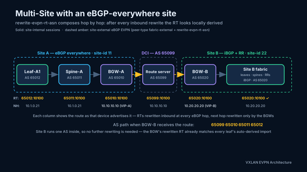
The figure traces that composed chain through the worked plan below, with Site A exploded into its eBGP-everywhere variant — leaf AS 65012, spine AS 65011, BGW AS 65010. The RT is rewritten four times, once at each receiving eBGP hop: at the spine and the BGW inside Site A, then at the route server and BGW-B on the site-external legs. Site B — one AS inside — needs no rewriting at all. Externally nothing changes: the rest of the world still sees Site A as AS 65010, because the BGW tier’s ASN is the site’s ASN. The internal legs are the only difference between the two internal models — the BGW re-origination (VIP next hop, site-id:VNI secondary RD) and the section 14 forwarding walks are identical whichever way each site is built.
Two planning rules round this out. First, only stretched VNIs need any cross-site RT agreement at all — a local-only VNI keeps its site-local RTs and is simply never configured on the BGWs (the selective-advertisement boundary of section 13.6). Second, keep VNI numbering identical in all sites: with either RT design above, the VNI is the only globally significant service identifier left. Recent NX-OS releases document an asymmetric-VNI mapping option for Multi-Site, but treat that as a migration exception to plan around, not a default.
A worked two-site numbering plan
Pulling the pieces together, using the section 15 tenant so the numbers line up:
                     Site A                 Site B
Site ID:             11                     22
Fabric AS:           65010 (iBGP + RR)      65020 (iBGP + RR)
BGW PIPs:            10.1.0.11, .12         10.2.0.11, .12
Multi-Site VIP:      10.10.10.10            10.20.20.20
Route servers:       AS 65099, loopbacks 10.99.0.1 / 10.99.0.2

Stretched L2 VNI 10100 — one Type-2 route travelling A → B
(auto-RT + rewrite-evpn-rt-asn on every site-external session):

  Leaf in A exports                RT 65010:10100, RD 10.1.0.21:32867
  BGW-A re-originates              next hop 10.10.10.10, RD 11:10100
  Route server rewrites inbound    RT 65099:10100
  BGW-B rewrites inbound           RT 65020:10100  → matches B's auto-derived import
  BGW-B re-originates inward       next hop 10.20.20.20
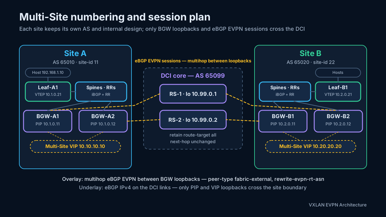
A Site B leaf therefore installs the host behind its local BGW VIP, with an RT that looks locally derived — every field readable back to a design decision. The chain of rewrites and re-originations is exactly what show bgp l2vpn evpn displays at each step, which makes this design pleasantly debuggable: the section 7.4 habit of reading RT:<ASN>:<VNI> out of the extended communities identifies which site’s view of the route you are looking at. A packet-level walk of the same path is in section 14, and the failure modes are in section 16. The Network Times, VXLAN EVPN Multi-Site
Multi-Site control-plane and data-plane walk
The section 12.2 walks showed multi-pod as one domain end to end. The same exercise across sites shows the opposite: every leg is a separate domain, and the identifiers change at each boundary. The route first — host 192.168.1.10 in Site A becoming reachable from Site B:
- Leaf
10.1.0.21(Site A) originates the Type-2 route: RD10.1.0.21:32867(primary, auto-derived), RT65010:10100, next hop10.1.0.21. The Site A route reflectors deliver it to every site VTEP, including both BGWs. - BGW-A1 and BGW-A2 re-originate it site-external. VNI 10100 is configured under their NVE, so it is eligible to cross (section 13.6). Both BGWs advertise the same re-originated route on their fabric-external sessions: next hop now
10.10.10.10(VIP-A), RD now the shared secondary11:10100, AS path65010. - The route servers relay it.
retain route-target allkeeps the route without importing it, the outbound route-map leaves the next hop at10.10.10.10, and the inboundrewrite-evpn-rt-asnhas made the RT65099:10100. BGW-B1 and BGW-B2 receive it with AS path65099 65010. - BGW-B1 and BGW-B2 import and re-originate it site-internal. Their inbound rewrite makes the RT
65020:10100— a match for their auto-derived import — and the route is re-advertised into Site B with next hop10.20.20.20(VIP-B), again under a site-scoped secondary RD rather than anything carried from Site A. - Site B leaves install it. Leaf
10.2.0.21imports on65020:10100and programs192.168.1.10behind10.20.20.20.
Notice what never happened: no Site B device learned 10.1.0.21, and no Site A router ID, internal RD, or VTEP prefix crossed the DCI unchanged. The underlay isolation of section 13.2 shows up here as a control-plane property before any packet moves.
The packet next — a Site B host sending to 192.168.1.10. Where the multi-pod data-plane walk had one tunnel, Multi-Site uses three, each built from a different table:
- Leaf
10.2.0.21matches the EVPN entry and encapsulates: outer10.2.0.21 → 10.20.20.20, VNI 10100. The VIP is anycast, so underlay ECMP delivers the packet to whichever Site B BGW is nearest. - That BGW decapsulates, looks the destination up again in VNI 10100, and finds the route from control-plane step 3: next hop
10.10.10.10. It re-encapsulates — sourced from its Multi-Site VIP, themultisite border-gateway interfaceloopback of section 15.8 — and the DCI underlay carries10.20.20.20 → 10.10.10.10to one of the Site A BGWs. - That BGW decapsulates, finds the site-internal route with next hop
10.1.0.21, and re-encapsulates a third time, sourced from its fabric-facing NVE loopback: destination10.1.0.21, still VNI 10100. - Leaf
10.1.0.21decapsulates and delivers the original frame to the host.
Return traffic walks the same three segments in reverse and may transit the other BGW at each site — the VIPs are anycast and bridging keeps no per-flow state, so per-direction asymmetry between a site’s BGWs is normal. The designated-forwarder election of section 13.4 exists for BUM only; known unicast, as here, never consults it.
The same walk in an eBGP-everywhere site. Rebuild Site A internally as the section 12.2 Model B — leaf AS 65012, spine tier AS 65011, BGW tier AS 65010, the same ASNs as the RT rewrite-chain figure earlier in this section:
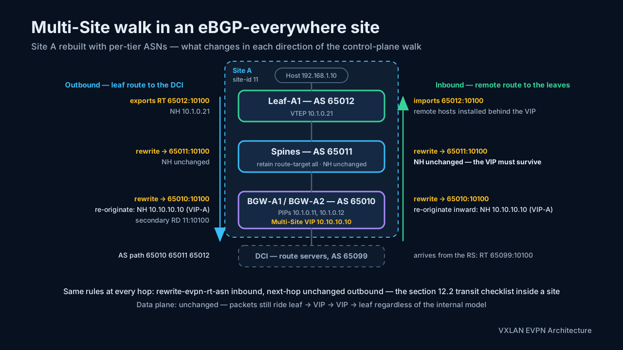
Only the site-internal legs of the control-plane walk change:
- Leaf
10.1.0.21(AS 65012) originates the same NLRI — RD10.1.0.21:32867, next hop10.1.0.21— but its auto-derived RT is now65012:10100, and the route reaches the spines over eBGP rather than through route reflectors. - The spine tier (AS 65011) plays the section 4.1 transit role:
retain route-target allkeeps the route, the outbound route-map leaves the next hop at10.1.0.21, the AS path grows, and the inbound rewrite makes the RT65011:10100. - The BGWs (AS 65010) rewrite once more to
65010:10100and import. From here the walk is identical to steps 2–5 of the main walk — re-origination behind VIP-A, secondary RD11:10100— except that the AS path advertised into the DCI is now65010 65011 65012, so BGW-B receives65099 65010 65011 65012: the site’s internal tiers become visible in the path. - The inbound direction adds one requirement worth noticing. When the BGWs re-originate a remote-site route inward with next hop
10.10.10.10(VIP-A), that VIP next hop must survive the eBGP trip down through the spine tier to the leaves — the same next-hop-unchanged policy that protects leaf VTEPs in section 12.2 now also protects the BGW VIP. The RT chain runs downhill the same way,65010 → 65011 → 65012, until it equals the leaf’s auto-derived import.
The data-plane walk does not change by a single byte: the leaf still encapsulates toward its local VIP and the BGWs still stitch the three tunnels — the site-internal BGP model is invisible to packets. It only decides which machinery delivers the routes, and therefore which of the section 12.2 failure modes apply inside each site. Section 14 extends these walks to inter-site routing and BUM replication.
12.4 Multi-pod versus Multi-Site at the boundary
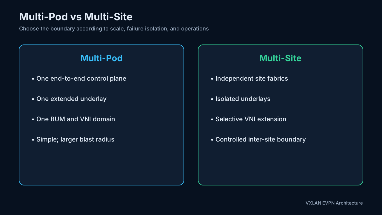
The two models differ less in topology than in what happens to identifiers and state at the seam:
| Boundary property | Multi-Pod | Multi-Site |
|---|---|---|
| Underlay | One reachability domain; every VTEP loopback everywhere | Isolated per site; only BGW PIP/VIP loopbacks cross the DCI |
| Overlay sessions | One EVPN domain (RR hierarchy or eBGP transit tiers) | eBGP EVPN only between BGWs or route servers |
| ASN plan | One fabric plan: single AS, or per-pod/per-leaf ASNs | Independent AS per site; eBGP mandatory between sites |
| RD | Per-VTEP rd auto, unique fabric-wide | Per-VTEP inside a site; re-originated as site-id:VNI at the BGW |
| RT | One fabric-wide plan (auto, or section 7.4 options) | Per-site plans plus explicit global RTs or rewrite-evpn-rt-asn |
| EVPN next hop | Originating VTEP, end to end | Rewritten to the Multi-Site VIP at each site boundary |
| BUM | One replication domain spanning all pods | Replicated per site; the DF BGW sends one controlled copy per remote site |
| Blast radius | Fabric-wide | Contained per site |
Choose multi-pod when the operational simplicity of one domain outweighs the larger blast radius. Choose Multi-Site when isolation, independent change control, and selective inter-site extension are more important.
13. VXLAN Multi-Site architecture
Multi-Site preserves independent intra-site VXLAN EVPN fabrics while connecting selected Layer 2 and Layer 3 services across a data-center interconnect (DCI).
Unlike VXLAN and EVPN themselves, VXLAN EVPN Multi-Site is a Cisco architecture with platform-specific control-plane and forwarding behavior. Treat its PIP/VIP advertisements, route re-origination, tracking, and supported feature combinations as NX-OS implementation details, not generic RFC 7432 behavior.
13.1 Border gateway roles
A Border Gateway (BGW) is the key component. It participates in the local site’s EVPN fabric and in the inter-site control and data planes. Its responsibilities include:
- Re-originating selected EVPN routes between site-local and inter-site domains.
- Terminating and originating inter-site VXLAN tunnels.
- Controlling which L2 VNIs and L3 VNIs extend across the DCI.
- Preventing loops and unnecessary BUM propagation.
- Preserving site isolation while providing reachability.
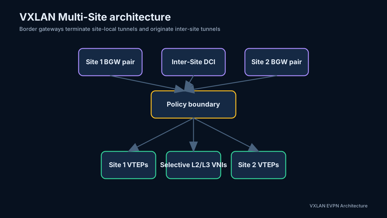
Each site keeps its local VTEP addressing, route-reflection design, and underlay. Remote sites do not need direct underlay routes to every internal VTEP; they reach the remote site’s BGW function.
13.2 Underlay isolation
The DCI carries reachability between border gateways, not a merger of every site’s internal underlay. This limits failure propagation and keeps internal VTEP prefixes private to a site.
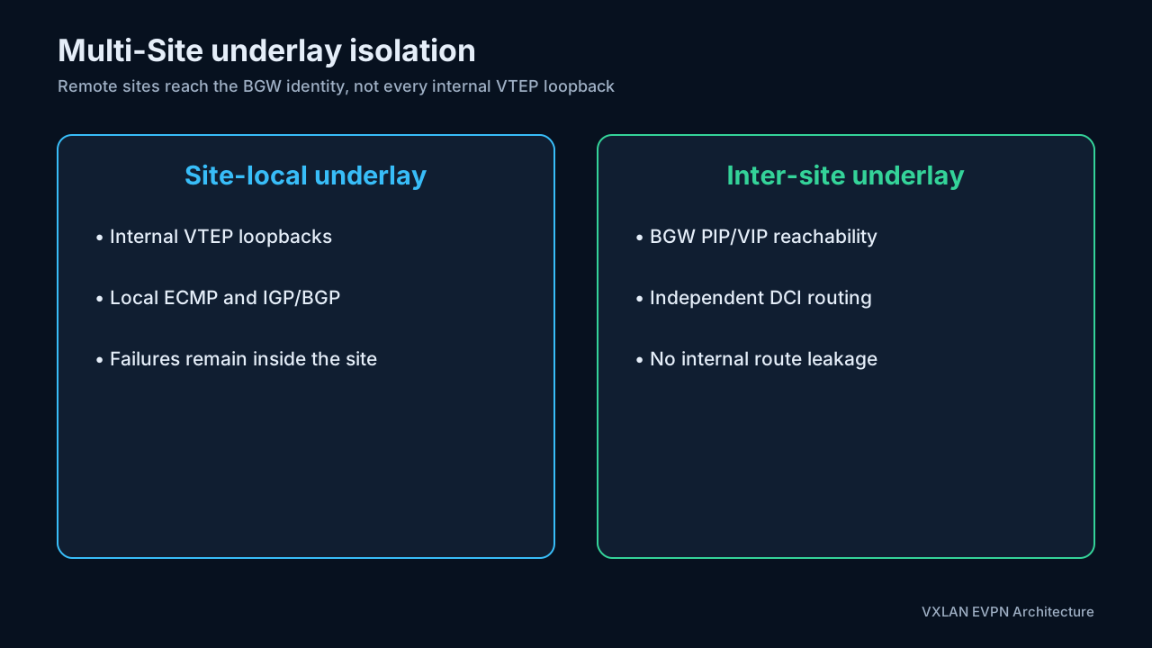
13.3 PIP and Multi-Site VIP
A BGW uses more than one tunnel identity:
- The PIP (Primary/Physical IP) identifies an individual BGW and is useful for traffic that must target that device specifically.
- The Multi-Site VIP is shared by the site’s BGWs and represents the anycast border-gateway function to remote sites.
Remote BGWs can therefore send ordinary inter-site traffic to a site-level anycast VTEP while retaining individual reachability when a function requires the PIP.
The PIP/VIP choice is feature-dependent. Some designs advertise PIP reachability for individual next-hop selection, external connectivity, CloudSec, or specialized traffic engineering. Commands such as advertise-pip, fabric-advertise-pip, and dci-advertise-pip have release-, topology-, and underlay-specific restrictions. Do not infer the correct behavior from the command names alone.
13.4 Anycast BGW and designated forwarder
A site normally deploys multiple BGWs for redundancy. They share the Multi-Site VIP but retain individual PIPs. For multi-destination traffic, a designated-forwarder election ensures only the correct BGW forwards a given copy, preventing duplicate delivery.
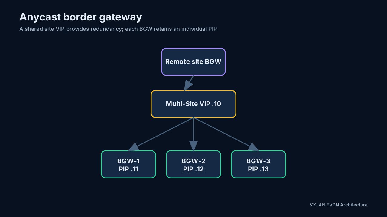
13.5 BUM replication modes
Multi-Site can use different replication mechanisms inside and between sites. For example, a site may use multicast internally while the DCI uses ingress replication. The BGW translates the replication behavior at the boundary.
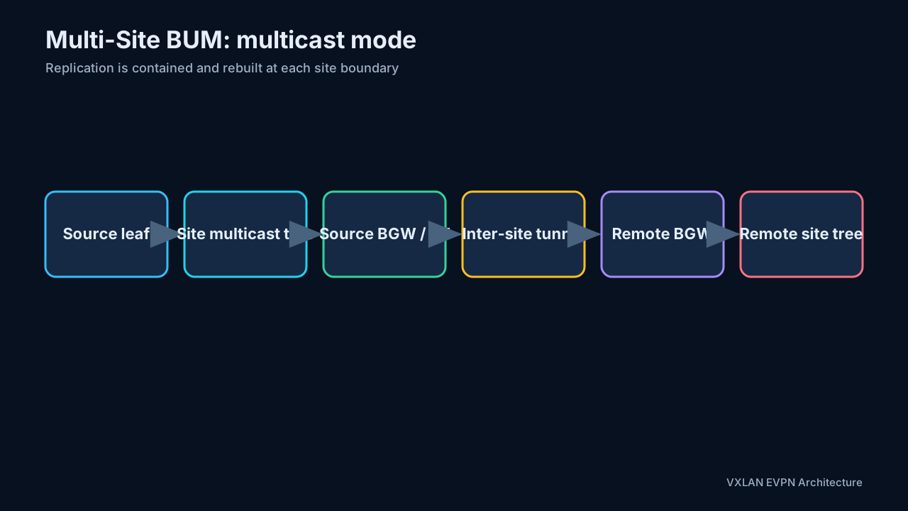
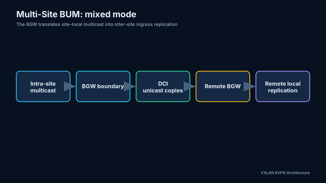
13.6 Selective advertisement
Only VNIs configured and permitted on the BGW should cross the DCI. Selective advertisement improves scale and security:
- A local-only tenant does not consume remote-site state.
- A stretched L2 segment can be permitted without exposing unrelated segments.
- A tenant L3 VNI can extend routed reachability while its access VLANs remain local.
The BGW is therefore a policy boundary, not merely a tunnel relay.
13.7 Multi-Site control-plane boundaries
A robust design separates three adjacency scopes:
- Intra-site underlay: provides reachability among local leaves, spines, route reflectors, and BGW fabric-facing identities.
- Intra-site EVPN overlay: distributes local endpoint and tenant routes between site VTEPs and local BGWs.
- Inter-site underlay and EVPN overlay: provides DCI reachability and exchanges only the EVPN routes selected for extension.
BGWs re-originate routes at the boundary so remote sites see the site-level BGW next hop rather than every internal leaf. This limits underlay state and creates a clean failure boundary. A design that merely extends the same route-reflector and VTEP domain across sites is closer to Multi-Pod than Multi-Site.
13.8 Tracking and restoration
evpn multisite fabric-tracking identifies links toward the local fabric; evpn multisite dci-tracking identifies links toward the inter-site network. Tracking allows a BGW to stop acting as a usable transit node when it loses one side of the path. delay-restore time delays restoration after recovery so control-plane and forwarding state can stabilize before the BGW attracts traffic.
The site ID must be identical on all BGWs in one site and different between sites. Current Cisco guidance also requires explicit planning for NVE source loopbacks and the BGW VIP, with underlay reachability for both where applicable. Cisco, Configure VXLAN EVPN Multi-Site
14. Multi-Site forwarding walks
14.1 Inter-site bridging
For two hosts in the same stretched L2 VNI but different sites:
- The local leaf forwards the frame toward its site BGW using the intra-site VXLAN overlay.
- The BGW terminates the intra-site tunnel.
- It applies inter-site policy and re-encapsulates toward the remote site’s Multi-Site VIP.
- A remote BGW decapsulates and sends a new intra-site VXLAN packet toward the destination leaf.
- The destination leaf decapsulates and bridges the original frame to the host.
This is not one end-to-end tunnel. The BGWs divide the journey into independently controlled tunnel domains.
14.2 Inter-site routing
For hosts in different subnets or tenants with permitted reachability, symmetric IRB remains the basic model. Tenant routes are advertised through the L3 VNI, and the BGWs re-originate allowed reachability. Routing occurs in the tenant VRF while each site retains its own underlay.
14.3 Inter-site BUM
A local BUM frame is replicated within the source site and, if the VNI is stretched, to the selected BGW. The BGW sends controlled copies to remote sites. Each remote site then performs its own local replication. Split-horizon and DF logic prevent a copy from returning to its origin or being duplicated by parallel BGWs.
15. Representative Cisco NX-OS configuration model
My study lab is a two-site build; the following is the consolidated pattern from it. It is a pattern, not a paste-ready build.
The snippets intentionally show the configuration hierarchy, not a complete production configuration. They omit platform-specific TCAM carving, route policies, authentication, BFD, maximum-path settings, multicast RP configuration, QoS, telemetry, and management-plane hardening. Choose one documented NX-OS release as the source of truth and lab-test the exact switch image and line card.
15.1 Enable features
feature ospf
feature bgp
feature pim
feature interface-vlan
feature vn-segment-vlan-based
feature nv overlay
nv overlay evpn
Depending on the platform, additional commands enable fabric forwarding, NGOAM, or Multi-Site functions.
15.2 Underlay loopback and routed link
interface loopback0
  description ROUTER-ID_AND_VTEP
  ip address 10.1.1.2/32
  ip router ospf UNDERLAY area 0.0.0.0
  ip pim sparse-mode

interface Ethernet1/1
  description TO-SPINE
  no switchport
  ip address 10.11.12.2/24
  ip router ospf UNDERLAY area 0.0.0.0
  ip pim sparse-mode
  no shutdown
The lab uses OSPF and PIM in the underlay. A modern deployment may instead use eBGP underlay and ingress replication.
A dedicated VTEP loopback is generally preferable to reusing the BGP router ID. It makes tunnel-source migration, route policy, troubleshooting, and vPC/ESI-specific PIP/VIP behavior easier to reason about. Advertise it as a host route and ensure every ECMP path supports the overlay MTU.
15.3 Overlay BGP
router bgp 65001
  router-id 10.1.1.2
  neighbor 10.1.1.1
    remote-as 65001
    update-source loopback0
    address-family l2vpn evpn
      send-community
      send-community extended
      route-reflector-client
The route-reflector-client line belongs on a route reflector, not on an ordinary leaf. A leaf’s equivalent neighbor stanza omits it.
15.4 VLAN-to-VNI and tenant VRF
vlan 100
  vn-segment 10100

vlan 1111
  name TENANT1-L3VNI
  vn-segment 50111

vrf context Tenant-1
  vni 50111
  rd auto
  address-family ipv4 unicast
    route-target both auto
    route-target both auto evpn
15.5 Anycast gateway SVI
fabric forwarding anycast-gateway-mac 0000.2222.3333

interface Vlan100
  no shutdown
  vrf member Tenant-1
  ip address 192.168.1.254/24
  fabric forwarding mode anycast-gateway
The anycast gateway MAC and gateway IP must be consistent on all leaves that offer the subnet.
15.6 NVE interface
interface nve1
  no shutdown
  host-reachability protocol bgp
  source-interface loopback0

  member vni 10100
    ingress-replication protocol bgp

  member vni 50111 associate-vrf
With multicast replication, an L2 VNI membership can reference a multicast group instead of BGP ingress replication.
15.7 EVPN VNI policy
evpn
  vni 10100 l2
    rd auto
    route-target import auto
    route-target export auto
Automatic RT derivation is convenient inside one ASN. Across multiple autonomous systems or during migration, explicit RTs may be required so every site derives and imports compatible values — section 7.4 walks through what auto derives and how Nexus and Cumulus differ on cross-AS matching.
Remember that the RT controls route import, whereas the VNI controls data-plane service identification. Two VNIs do not become one broadcast domain merely because their numbers look related, and two VRFs do not exchange routes unless their import/export policy permits it.
15.8 Multi-Site BGW pattern
evpn multisite border-gateway 11
  delay-restore time 30

interface loopback100
  description MULTISITE-VIP
  ip address 10.10.10.10/32 tag 1234

interface nve1
  multisite border-gateway interface loopback100
  member vni 10100
    multisite ingress-replication

interface Ethernet1/2
  description DCI
  no switchport
  medium p2p
  evpn multisite dci-tracking

interface Ethernet1/3
  description FABRIC
  no switchport
  evpn multisite fabric-tracking
The site ID must be unique per site and identical across redundant BGWs in that site. DCI-facing and fabric-facing links are tracked separately so Multi-Site can react correctly to isolation and partial failures.
The current Cisco Multi-Site guide requires planning loopback addresses and confirming their underlay advertisement before enabling the BGW function. It also documents feature-specific restrictions—for example, some PIP advertisement combinations differ with vPC and IPv6 underlays—so this abbreviated template must not be used as a capability matrix. Cisco Multi-Site configuration guide
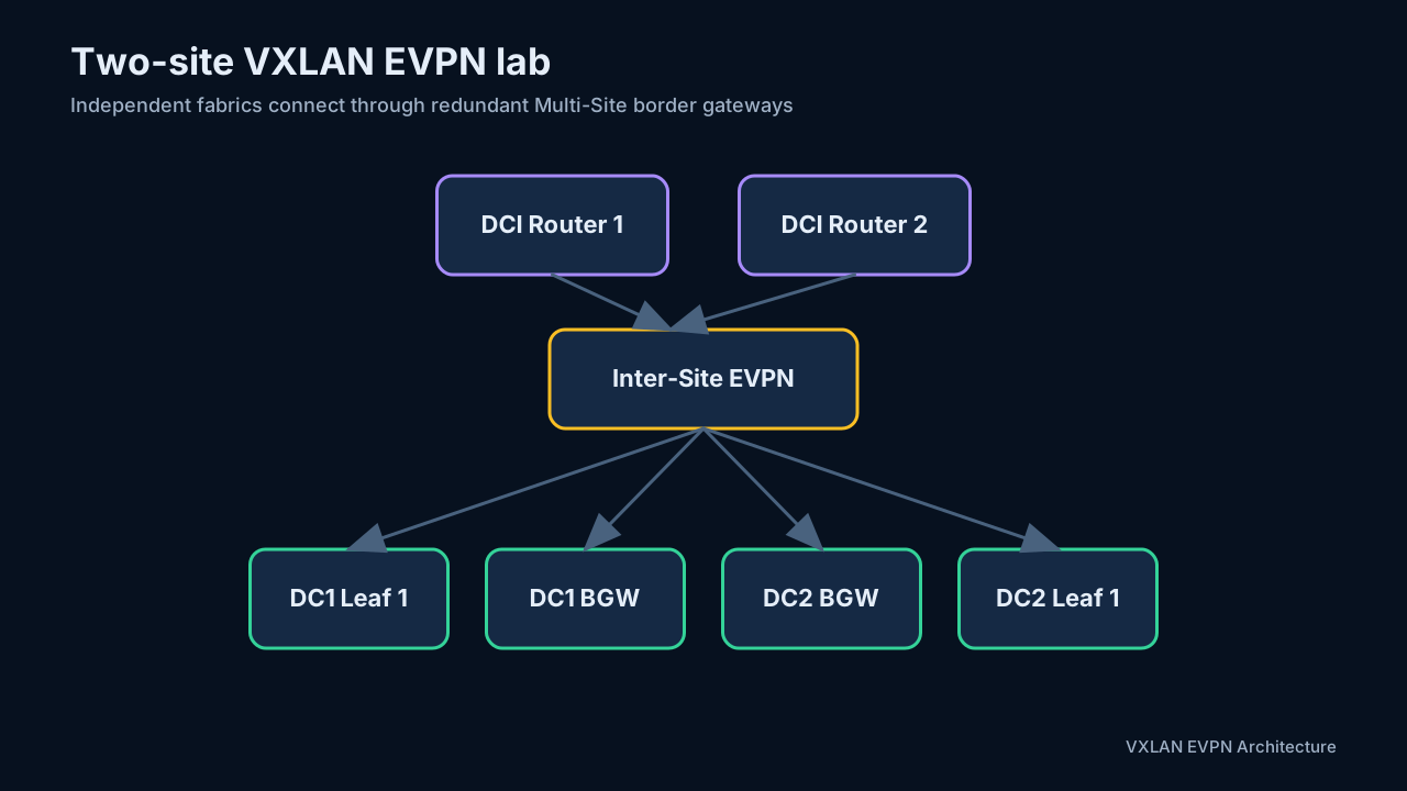
16. Failure handling and verification
Multi-Site should be tested for at least these events:
- A leaf-to-spine fabric link fails.
- One BGW loses all fabric-facing links.
- One BGW loses its DCI-facing links.
- A BGW reloads and returns.
- An underlay route to a VTEP or VIP disappears.
- A host moves within a site or between sites.
- A route reflector becomes unavailable.
Fabric tracking and DCI tracking help a BGW decide whether it is still a valid transit point. Delay-restore timers prevent a recovering device from advertising reachability before its forwarding state is ready.
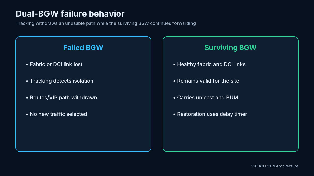
Useful verification commands include:
show bgp l2vpn evpn summary
show bgp l2vpn evpn
show bgp l2vpn evpn route-type 2
show bgp l2vpn evpn route-type 3
show bgp l2vpn evpn route-type 5
show nve peers
show nve vni
show nve multisite fabric-links
show nve multisite dci-links
show mac address-table dynamic
show ip arp vrf <vrf-name>
show forwarding route vrf <vrf-name>
Interpret the evidence by control-plane object:
| Symptom | Route/state to inspect | Typical root causes |
|---|---|---|
| Remote host MAC missing | Type 2 MAC route, MAC-VRF import RT | Local host never learned, export RT mismatch, BGP path rejected, unresolved VTEP next hop |
| MAC exists but ARP suppression misses | Type 2 MAC/IP route, suppression cache | Type 2 carries no IP, silent host, SVI/suppression mismatch, TCAM/platform limitation |
| BUM reaches no remote VTEPs | Type 3 IMET and NVE replication list | VNI not active, RT mismatch, missing PMSI tunnel information, multicast RPF failure |
| Multihomed next hop is not load-balanced | Type 1 per-EVI and Type 2/ESI state | ESI mismatch, A-D route absent, single-active mode, aliasing unsupported or filtered |
| Duplicate BUM at multihomed device | Type 4, DF state, split-horizon state | Inconsistent ESI, DF disagreement, missing ES-import policy, transient convergence |
| Prefix is visible but not installed | Type 5 plus overlay-index recursion | Missing RT-2/RT-1 dependency, unresolved BGP next hop, wrong IP-VRF RT, unsupported model |
| Inter-site route stops at BGW | Re-originated EVPN route, PIP/VIP, tracking | VNI not extended, DCI policy, site-ID inconsistency, fabric/DCI tracking withdrawal |
A disciplined troubleshooting order is:
- Confirm physical links, MTU, and routed underlay adjacency.
- Confirm VTEP loopback and Multi-Site VIP reachability.
- Confirm EVPN BGP sessions and correct address-family activation.
- Check Type 3 membership before debugging BUM replication.
- Check Type 2 MAC/IP routes for endpoint reachability.
- Check Type 5 and VRF import policy for prefix reachability.
- Verify VLAN-to-VNI, VRF-to-L3-VNI, RD, and RT mappings.
- Inspect the NVE peer and local MAC/ARP tables.
- Capture the packet and compare inner versus outer headers.
17. Inter-tenant (east–west) firewall insertion
VXLAN EVPN isolates tenant VRFs by default. Connecting tenants is a policy decision. This section and section 18 answer two different questions that are easy to conflate, because both involve a firewall at a border or service leaf:
- This section — east–west: when tenant RED must talk to tenant BLUE, how is that inter-tenant traffic steered through a stateful inspection point instead of being routed directly?
- Section 18 — north–south: how does each tenant reach the Internet or WAN? The firewall there does per-tenant edge policy and NAT; it does not answer the inter-tenant question — 18.3’s RT policy keeps tenants from learning each other’s routes through the shared VRF, and the residual hairpin path through that VRF’s own table needs its own policing (see 18.3).
The same physical firewall cluster often serves both roles — the appliance doing tenant NAT toward the WAN can also hold the inter-tenant zones — but the two designs are configured and reasoned about independently.
The rest of this section builds the insertion end to end with the same tenants as section 18: RED (10.10.0.0/16, L3 VNI 50001) and BLUE (10.20.0.0/16, L3 VNI 50002). In my lab build the inspection point is an ASAv pair; any stateful firewall fits the same design. Two questions must be answered, and they structure the subsections:
- Plumbing (17.1): how does the service leaf hand traffic between a tenant VRF and the firewall?
- Steering (17.2): how do all the other leaves learn to send inter-tenant traffic toward that service leaf in the first place?
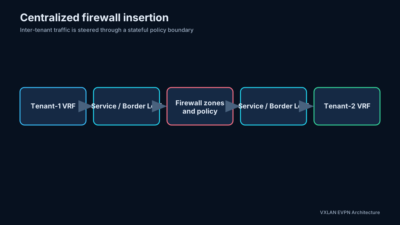
17.1 The transit plumbing: two attachment designs
The firewall needs one routed leg per tenant VRF — a RED leg and a BLUE leg — so that each firewall zone maps to exactly one tenant. Each leg is a small transit segment between the service leaf and the firewall, and there are two standard ways to build it:
Design A — transit VLAN + SVI. The service leaf bridges a dedicated VLAN toward the firewall and terminates it on an SVI inside the tenant VRF:
vlan 3801                          ! RED transit — L2 only, no hosts
interface vlan 3801
  vrf member RED
  ip address 172.16.1.1/29

interface Ethernet1/48             ! trunk toward the firewall
  switchport mode trunk
  switchport trunk allowed vlan 3801-3802
The firewall’s RED interface lives in the same subnet — 172.16.1.4/29, a floating IP across the HA pair. Because this leg is a bridge domain, it accommodates firewall HA pairs and vPC-attached appliances, and the transit VLAN can even be stretched through an L2 VNI when the standby unit sits behind a different leaf.
Design B — routed subinterface. No bridge domain at all — a dot1q subinterface on a routed port, structurally the same as the external handoff in 18.1:
interface Ethernet1/48.3801
  encapsulation dot1q 3801
  vrf member RED
  ip address 172.16.1.0/31         ! firewall RED leg: 172.16.1.1/31
Point-to-point, fastest convergence, simplest to reason about — but it single-attaches the firewall to that one leaf.
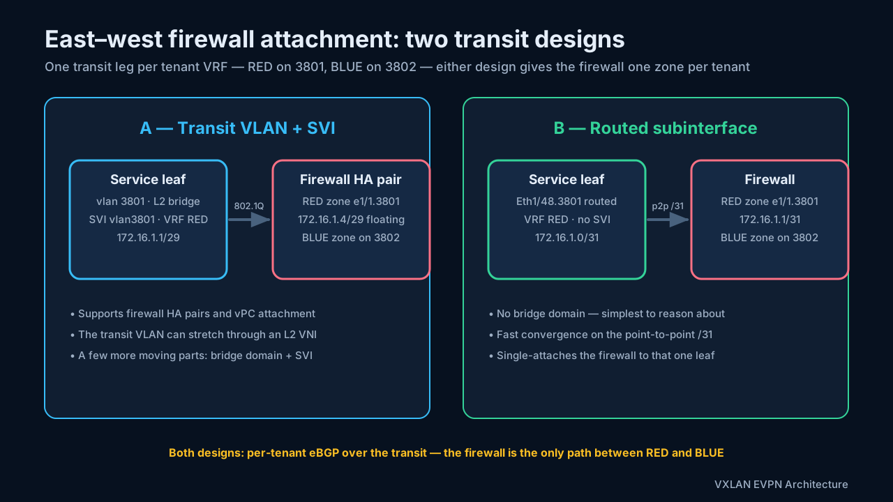
BLUE mirrors the same construction on tag 3802 and 172.16.2.x. In either design, three properties hold:
- The transits are pure plumbing: no hosts, no anycast gateway, no VLAN-to-VNI mapping (unless a Design-A VLAN is deliberately stretched).
- The tags (
3801,3802) and subnets (172.16.1.x,172.16.2.x) exist only on the leaf–firewall link; they never appear in the fabric (again, unless a Design-A transit is deliberately stretched). - One tenant = one leg = one firewall zone. A shared leg would collapse the zone model.
17.2 Routing and steering
Over each transit leg, the service leaf runs a routing exchange inside the tenant VRF. eBGP is typical — firewall AS 65200 against the fabric’s 65000; static routes work for small designs:
BGP in VRF RED     neighbor 172.16.1.4  remote-as 65200   advertise 10.10.0.0/16
BGP in VRF BLUE    neighbor 172.16.2.4  remote-as 65200   advertise 10.20.0.0/16

(with Design-B /31 addressing the neighbors are 172.16.1.1 and 172.16.2.1)
The firewall now knows both tenants — RED through its RED leg, BLUE through its BLUE leg — and advertises each tenant’s prefixes into the other tenant’s session, subject to policy.
One eBGP detail is mandatory here, because the U-turn trips AS-path loop prevention. The service leaf originates 10.10.0.0/16 toward the firewall with AS 65000 in the path; when the firewall re-advertises that route into the BLUE session on the same leaf, the path arrives as 65200 65000 — the leaf sees its own AS and silently rejects the route. Without a fix, the cross-tenant route is never installed, no Type-5 is ever re-originated, and inter-tenant traffic simply never flows. Use one of:
allowas-in 1on the per-VRF firewall neighbors at the service leaf,as-overrideon the firewall — or have the firewall originate its own aggregates instead of re-advertising, or- static routes over the transits instead of eBGP, which sidestep the problem entirely.
With that in place, steering across the whole fabric follows:
- In VRF RED, the service leaf learns
10.20.0.0/16from the firewall over the RED transit. - It re-originates that route into EVPN as a Type-5 with RED’s RT and L3 VNI.
- Every RED leaf now resolves BLUE-bound destinations to the service-leaf VTEP — the fabric itself steers inter-tenant traffic to the insertion point.
The mirror happens in VRF BLUE with 10.10.0.0/16. Neither tenant ever imports the other’s Route Target — the only cross-tenant path is through the firewall.
17.3 Packet walk
RED host 10.10.1.20 sends to BLUE host 10.20.2.30:
- The RED leaf’s VRF lookup matches the Type-5 route for
10.20.0.0/16; the next hop is the service-leaf VTEP. - The packet crosses the fabric in RED’s L3 VNI
50001. - The service leaf decapsulates, looks up VRF RED, and forwards over the RED transit to the firewall — this is the hop where Designs A and B differ, unpacked below.
- The firewall applies RED→BLUE zone policy and, if permitted, routes the packet out its BLUE leg back to the service leaf.
- The service leaf receives it in VRF BLUE, resolves the destination through EVPN, and encapsulates in BLUE’s L3 VNI
50002toward the destination leaf. - The destination leaf decapsulates and delivers the packet to
10.20.2.30.
Step 3 with Design A (transit VLAN + SVI) — routing into a bridge domain. The part that looks like magic is ordinary last-hop behavior: the route delivers the packet to the SVI, then the bridge domain delivers the frame to the firewall’s MAC.
- The VRF RED lookup returns
10.20.0.0/16 → next hop 172.16.1.4(the firewall’s floating IP, learned over eBGP). That next hop falls inside172.16.1.0/29— the connected subnet of SVI vlan3801 — so the egress interface is the SVI. - The leaf resolves
172.16.1.4with ARP inside VLAN 3801, out the trunk. The active firewall unit answers with its MAC (the floating IP always belongs to the active unit). - The leaf writes a fresh Ethernet header — source MAC = the SVI’s MAC, destination MAC = the firewall’s MAC, 802.1Q tag
3801— and bridges the frame out the trunk port. - On the wire this is now a plain tagged Ethernet frame; the VXLAN encapsulation ended at decapsulation in step 3 of the main walk. The firewall receives it on
e1/1.3801, strips the tag, and processes it in the RED zone.
Note what the customer’s traffic does not do: it never rides its original VLAN or L2 VNI onto this link. After the VRF lookup, the tenant frame’s original L2 context is gone — only the inner IP packet continues, re-framed for VLAN 3801. The transit VLAN carries routed tenant packets, not the tenant’s bridge domain.
This mechanism is also exactly why Design A handles firewall HA cleanly. On failover, the standby unit takes over 172.16.1.4 and sends gratuitous ARP; the leaf updates its ARP and MAC entries, and no routing changes at all — the next hop is still 172.16.1.4. And if the standby sits behind a different leaf with the transit VLAN stretched through an L2 VNI, this same bridged frame is VXLAN-bridged (L2 VNI, not L3) across the fabric to that leaf — still the same routed next hop, just a longer bridge domain.
Step 3 with Design B (routed subinterface). The same lookup resolves next hop 172.16.1.1 out point-to-point subinterface Eth1/48.3801. There is no bridge domain, no MAC table, no flooding — the frame is tagged 3801 and handed straight to the single peer on the /31. Routing-wise the walk is identical to Design A; only the final-hop delivery is simpler (and the firewall is single-attached).
Step 4, both designs. The firewall’s return hop onto the BLUE leg mirrors the same mechanics: it routes toward the service leaf’s BLUE address (172.16.2.1), resolves it on its BLUE subinterface, and the leaf receives the frame on the BLUE transit — landing the packet in VRF BLUE.
Return traffic retraces the path in mirror image: BLUE leaf → Type-5 → service leaf → firewall BLUE zone → RED zone → VRF RED → RED host. Both directions traverse the same firewall state, because in each VRF the only route to the other tenant points at the firewall.
17.4 Operational controls
- Keep each tenant in a distinct firewall zone or subinterface; never share a leg between tenants.
- Filter both directions: advertise only tenant summaries to the firewall, and accept back only the expected remote-tenant prefixes (or a default).
- Never RT-import tenants into each other while inspection is mandatory. A direct leak does not merely bypass the firewall — it can create an asymmetric path where one direction is inspected and the other is not, which breaks every stateful session.
- Mind the steering-route lifecycle. With eBGP, the re-originated Type-5s withdraw automatically when the firewall session drops — flows then fail at the ingress leaf with a clean unreachable, and a standby insertion point (if one exists) can take over. With static routes toward the firewall, add object tracking so the statics — and the Type-5s derived from them — disappear when the firewall stops responding.
- For firewall pairs, use active/standby with session synchronization — or ensure ECMP hashing cannot split a flow’s two directions across independent units.
- Keep the transit interfaces out of host designs: no endpoints, no anycast gateway, no suppression features on those segments.
The design is centralized from the policy perspective, even though endpoints and gateways remain distributed. And when a specific tenant pair is trusted enough to skip inspection, the cross-VRF RT-import mechanics of 18.3 can connect them directly — uninspected by construction, so make that a deliberate, per-pair decision.
18. External connectivity: per-VRF handoff, fusion router, and shared services
A VXLAN EVPN fabric isolates tenant VRFs by default; reaching the Internet or WAN is a deliberate design decision, not a side effect. There are three standard options for the external handoff:
- Per-VRF routed handoff at a border-leaf pair — every tenant VRF gets its own eBGP session to the external edge. Recommended, and detailed in 18.1.
- Fusion router — the border keeps its VRFs, but the external sessions terminate in the edge device’s global routing table (18.2).
- Shared Internet VRF — one services VRF owns external reachability, and selected routes are leaked between it and the tenants at designated border leaves (18.3 — the model my lab builds).
To keep the comparison concrete, this section reuses one worked example throughout:
- 3 tenant VRFs: RED, BLUE, GREEN
- 20 VLANs and L2 VNIs in each VRF — 60 L2 VNIs in total
- A pair of VXLAN EVPN border leaves, BL1 and BL2
- eBGP from the border leaves to an external edge router or firewall
The headline result up front: you do not need 60 external BGP sessions. The external handoff happens at the VRF level — 60 L2 VNIs stay inside the fabric, while the border presents only 3 L3 VNIs and 3 eBGP sessions per border-to-edge link.
18.1 Option 1: per-VRF eBGP handoff at a border-leaf pair
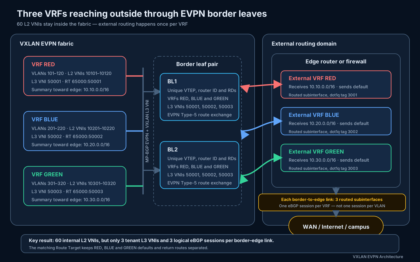
| Tenant | Internal subnets | VLANs | L2 VNIs | L3 VNI | Route Target | External summary |
|---|---|---|---|---|---|---|
| RED | Twenty VLANs under 10.10.0.0/16 | 101–120 | 10101–10120 | 50001 | 65000:50001 | 10.10.0.0/16 |
| BLUE | Twenty VLANs under 10.20.0.0/16 | 201–220 | 10201–10220 | 50002 | 65000:50002 | 10.20.0.0/16 |
| GREEN | Twenty VLANs under 10.30.0.0/16 | 301–320 | 10301–10320 | 50003 | 65000:50003 | 10.30.0.0/16 |
The numbering follows the conventions used elsewhere in this post: L2 VNI = 10000 + VLAN (section 2.3), and one L3 VNI per tenant VRF in the 5000x family (section 10.2).
Each server leaf that hosts RED networks has the following logical configuration, and the same pattern applies to BLUE and GREEN:
VRF RED
  L3 VNI 50001
  Import/export RT 65000:50001
  VLAN-to-L2-VNI mappings for locally attached RED networks
  Anycast gateway on each local RED VLAN
The border-leaf model. Each border leaf joins all three tenant VRFs:
Border leaf BL1
  Underlay
    Unique router ID
    Unique VTEP loopback
    Routed links to the spines
    VTEP loopback advertised through the underlay

  EVPN overlay
    MP-BGP EVPN session to route reflectors or overlay peers
    VXLAN encapsulation enabled
    Extended communities exchanged

  VRF RED    — L3 VNI 50001, unique RD, import/export RT 65000:50001
  VRF BLUE   — L3 VNI 50002, unique RD, import/export RT 65000:50002
  VRF GREEN  — L3 VNI 50003, unique RD, import/export RT 65000:50003
BL2 uses the same VRFs, L3 VNIs and Route Targets, but its own VTEP IP, router ID, Route Distinguishers, external interface addresses and BGP sessions.
For a normal symmetric-IRB Layer 3 handoff, the border leaves need the three tenant VRFs and three L3 VNIs — not all 60 L2 VNIs. The exceptions that do pull L2 VNIs onto the border:
- A Layer 2 handoff to the outside.
- Servers or service appliances attached directly to the border.
- A local firewall interface using those VLANs.
- A network operating system that requires the L2 VNIs to be present.
The border leaves still learn the necessary tenant host and prefix routes through EVPN.
Physical and logical handoff. Separate physical interfaces per VRF work, but one physical link carrying three routed IEEE 802.1Q subinterfaces is the common pattern. Between BL1 and Edge1:
| Subinterface | 802.1Q tag | VRF | BL1 address | Edge1 address |
|---|---|---|---|---|
| Ethernet1/49.3001 | 3001 | RED | 172.31.1.0/31 | 172.31.1.1/31 |
| Ethernet1/49.3002 | 3002 | BLUE | 172.31.2.0/31 | 172.31.2.1/31 |
| Ethernet1/49.3003 | 3003 | GREEN | 172.31.3.0/31 | 172.31.3.1/31 |
These are routed subinterfaces, not Layer 2 VXLAN extensions — no VNI maps to tags 3001–3003; they exist only on the handoff link. The external router or firewall has matching subinterfaces in its corresponding routing contexts. (A firewall here plays the north–south role — per-tenant edge policy and NAT. If the same appliance also inspects tenant-to-tenant traffic, that is the separate east–west insertion design of section 17; the roles can share hardware but not a design.)
Per-VRF eBGP. With fabric AS 65000 and external edge AS 65100, each border leaf runs one logical eBGP session inside each VRF:
BGP in VRF RED     neighbor 172.31.1.1  remote-as 65100
BGP in VRF BLUE    neighbor 172.31.2.1  remote-as 65100
BGP in VRF GREEN   neighbor 172.31.3.1  remote-as 65100
The edge router mirrors these sessions from its per-tenant routing contexts. The exact syntax differs between NX-OS, EOS, Junos, IOS-XE and FRR, but the logical structure is the same.
Outside routes into EVPN. The edge router or firewall normally sends a default route into every tenant VRF. On each border leaf:
- The default arrives through the IPv4-unicast BGP address family inside the tenant VRF.
- Depending on the platform, an explicit advertise statement or export policy selects — or merely filters — the route for EVPN. Some NOSes (NX-OS, EOS with the EVPN export RT configured) export BGP-learned VRF routes automatically; others (IOS-XE
advertise l2vpn evpn, Junos export policy) require the explicit step. - The border advertises the default as an EVPN Type-5 route (RFC 9136).
- The Type-5 route carries the tenant Route Target, L3 VNI, border VTEP next hop and overlay router MAC.
0.0.0.0/0, RT 65000:50001, L3 VNI 50001, next hop BL1
0.0.0.0/0, RT 65000:50002, L3 VNI 50002, next hop BL1
0.0.0.0/0, RT 65000:50003, L3 VNI 50003, next hop BL1
A RED leaf imports only the first default, because its RED IP-VRF imports 65000:50001. It does not import the BLUE or GREEN defaults — the Route Target is what keeps three coexisting default routes separated.
Fabric routes toward the outside. The border leaf imports EVPN tenant routes into the corresponding IP-VRF, and should normally advertise summaries rather than every host route:
VRF RED:    advertise 10.10.0.0/16
VRF BLUE:   advertise 10.20.0.0/16
VRF GREEN:  advertise 10.30.0.0/16
If a VRF’s twenty VLAN prefixes are not contiguous, advertise the individual subnet prefixes or several smaller summaries. The route policy per VRF follows this model:
| Direction | Policy |
|---|---|
| Edge to EVPN | Default route and approved external prefixes only |
| EVPN to edge | The tenant summary (for RED, 10.10.0.0/16) |
| Block | Host /32s and other tenants’ routes |
Important controls:
- Do not send an EVPN-learned default route back to the external edge.
- Use explicit prefix lists or route policies in both directions.
- Tag routes with BGP communities when useful for loop prevention.
- Advertise an aggregate only when the border has valid contributing reachability or an intentionally tracked summary route.
- Avoid placing a full Internet table in every fabric leaf unless the hardware scale has been deliberately validated.
Outbound packet flow. RED server 10.10.1.20 sends traffic to an Internet destination:
- The server sends the packet to its local RED anycast gateway.
- The local leaf performs a lookup in VRF RED.
- It finds RED’s EVPN Type-5 default route through BL1 and/or BL2.
- The leaf VXLAN-encapsulates the packet using L3 VNI
50001. - The outer destination is the selected border-leaf VTEP.
- A spine forwards the outer IP packet without looking up the tenant address.
- The border leaf receives and decapsulates the VXLAN packet.
- L3 VNI
50001selects VRF RED. - The border performs a native IP lookup and forwards the packet over RED’s external routed subinterface.
- The external firewall applies security policy and NAT when required.
BLUE follows the same physical infrastructure but uses L3 VNI 50002 and the BLUE routing table; GREEN uses 50003. The VRFs remain separate along the entire path.
Return packet flow. For traffic returning to RED server 10.10.1.20:
- The external router performs a lookup in external VRF RED.
- It finds
10.10.0.0/16through BL1 and BL2. - It selects a border and sends a native IP packet over the RED handoff.
- The border receives the packet in VRF RED.
- The border finds an EVPN Type-2 host route or Type-5 prefix route toward the server’s leaf.
- It VXLAN-encapsulates the packet using L3 VNI
50001. - The underlay forwards the packet to the destination leaf VTEP.
- The destination leaf decapsulates and forwards the packet to the server.
Border redundancy. Both BL1 and BL2 should advertise the default for each VRF while they have valid external reachability, so a RED server leaf can install an ECMP default:
0.0.0.0/0
  Next hop: BL1 VTEP
  Next hop: BL2 VTEP
With two border leaves and two external edge routers, fully connected:
3 VRFs × 2 border leaves × 2 edge routers = 12 external eBGP sessions
Still not one session per VLAN. Recommended redundancy controls:
- Enable EVPN and BGP multipath where required.
- Use unique border VTEP next hops and unique RDs.
- Use BFD or fast BGP failure detection.
- Make default-route origination conditional on actual external reachability.
- Withdraw a Type-5 default when a border loses all usable external paths.
- Test the failure of every external link, border leaf, spine and edge node.
18.2 Option 2: fusion router — merge tenants into the edge global table
The border retains its three VRFs, but the external sessions terminate in the edge device’s global routing table. An edge used this way is sometimes called a fusion router.
This is simpler to configure, but:
- Tenant addresses cannot overlap.
- The edge may route directly between tenants.
- Strong firewall or ACL policy is required to restore the isolation the fabric provided.
- Troubleshooting tenant separation becomes harder.
18.3 Option 3: shared Internet VRF with centralized route leaking
Instead of handing each tenant to the outside separately, one shared services VRF — call it INTERNET — owns external reachability, and selected routes are leaked between it and the customer tenant VRFs. Continuing the worked example: RED, BLUE and GREEN keep their L3 VNIs 50001–50003, and the INTERNET VRF gets its own L3 VNI 50900 with RT 65000:50900. Only the INTERNET VRF speaks eBGP to the outside; the customer tenants never do.
Naming note. My lab build implements a two-tenant version of this model and names the shared VRF Tenant-3 — a “tenant” in name only. That naming is misleading in production: the shared VRF is infrastructure, not a customer. Give it a role name —
INTERNET,SHARED-SVC,BORDER— so it stays visually distinct from customer tenants in configuration and troubleshooting output.
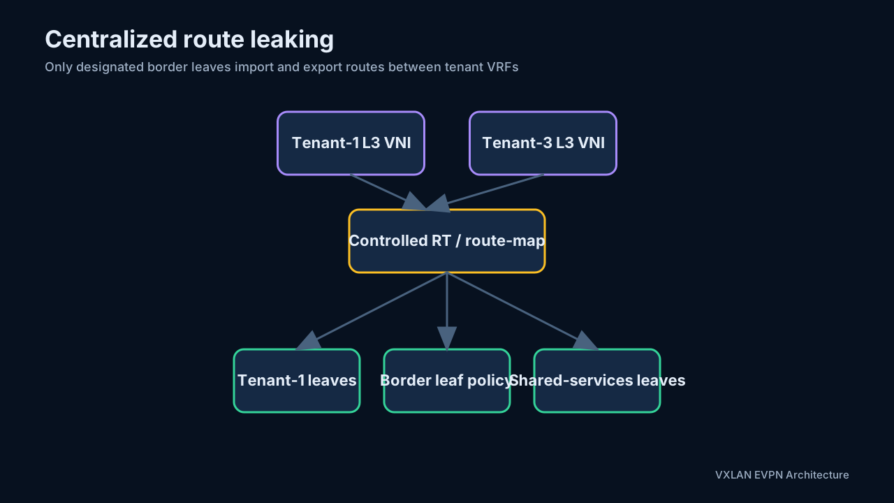
This option can reduce the external BGP-session count when there are hundreds of tenant VRFs — one external handoff serves them all — but route leaking and firewall policy become more complex. With only a handful of tenant VRFs, the per-VRF handoffs of 18.1 are normally cleaner.
Why centralize the leaking. If every leaf imports routes between tenant VRFs, policy is distributed throughout the fabric and becomes hard to audit. Centralized route leaking restricts the import/export logic to designated border leaves. Other leaves use EVPN to reach those border nodes.
The basic policy is:
- The INTERNET VRF learns or originates Internet/default reachability — a WAN-facing interface or an external eBGP peer.
- Each customer tenant — RED, BLUE and GREEN — imports only the routes it needs from INTERNET, normally just the default.
- INTERNET imports each tenant’s summary (
10.10.0.0/16,10.20.0.0/16,10.30.0.0/16) for the return path. - Route maps and RT policies prevent accidental full-mesh tenant connectivity — with one residual vector to close: a RED packet following its leaked default arrives in the INTERNET VRF, whose table also holds BLUE’s summary (imported for return traffic). More-specific beats default, so the border itself can hairpin RED→BLUE unless the edge firewall inspects that path or an explicit filter/PBR rule blocks tenant-to-tenant transit at the border.
Shared Internet model. RED, BLUE and GREEN each reach the Internet through the shared VRF while remaining isolated from one another. The border leaf performs the controlled leaking, and a WAN-facing interface or external peer supplies default reachability into INTERNET.
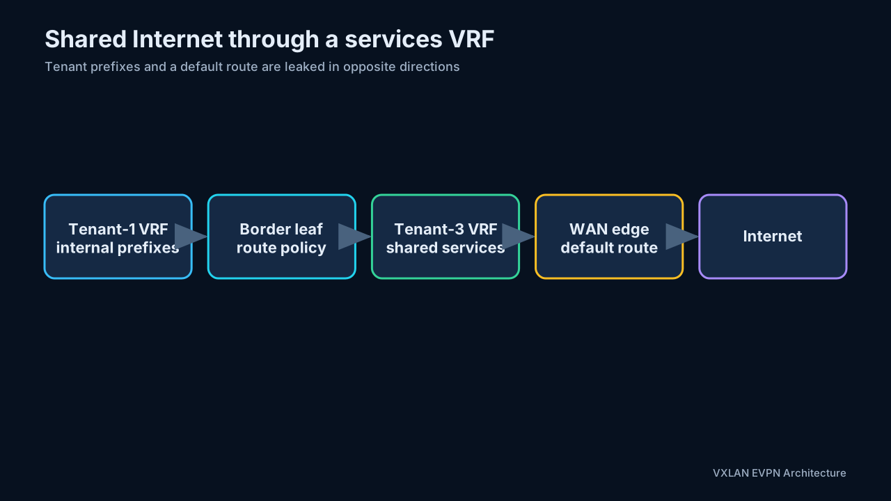
On NX-OS, leaking between two tenant-style VRFs is done with cross-VRF route-target imports plus filtering route-maps — a VRF imports the other VRF’s Route Target, and an import map restricts what actually lands in the RIB. Conceptually, with all three customer tenants:
ip prefix-list DEFAULT_ONLY seq 5 permit 0.0.0.0/0
route-map FROM_INTERNET permit 10
  match ip address prefix-list DEFAULT_ONLY

vrf context RED
  address-family ipv4 unicast
    route-target import 65000:50900 evpn   ! INTERNET's RT — pull its EVPN routes
    import map FROM_INTERNET               ! ...but install only the default

vrf context BLUE                           ! GREEN follows the same pattern
  address-family ipv4 unicast
    route-target import 65000:50900 evpn
    import map FROM_INTERNET

vrf context INTERNET
  address-family ipv4 unicast
    route-target import 65000:50001 evpn   ! RED's summary, for return traffic
    route-target import 65000:50002 evpn   ! BLUE's summary
    route-target import 65000:50003 evpn   ! GREEN's summary
    import map TENANT_SUMMARIES_ONLY
(NX-OS’s import vrf / export vrf commands serve a different case: they leak only between a tenant VRF and the default VRF — import vrf default map <map> advertise-vpn / export vrf default map <map> allow-vpn — useful when external reachability lives in the global table rather than a services VRF.)
The policy intent matters more than the particular syntax:
- Mark or match exported routes deterministically.
- Leak the default route only in the intended direction.
- Leak internal prefixes back toward the services VRF for return traffic.
- Prevent the imported route from being recursively re-exported and forming a loop.
- RED, BLUE and GREEN never import each other’s RTs. All three meet inside INTERNET, so the import maps must also stop one tenant’s prefixes from transiting the shared VRF into another tenant — that is the “accidental full-mesh” failure mode.
- Verify both the local VRF RIB and the EVPN Type 5 advertisements.
One structural caveat: because every tenant’s summary coexists in the single INTERNET RIB, customer address ranges must be unique — or per-tenant NAT must be applied at the edge before the shared table. Overlapping customer addressing is one more reason to prefer the per-VRF handoffs of Option 1.
18.4 Common route-leaking failures
If the route appears in BGP EVPN but not in the tenant RIB, inspect the RT import policy, route-map, next-hop resolution, and route type. If forward traffic works but replies fail, the services VRF or firewall probably lacks a return route. If a default route appears on unintended tenants, the export match is too broad.
18.5 Choosing between the options
For a small number of tenant VRFs, use Option 1:
- Two dedicated border leaves.
- One L3 VNI per VRF.
- One routed subinterface and one eBGP session per VRF per border-to-edge link.
- A Type-5 default route from the edge into each tenant VRF.
- Summarized tenant prefixes from EVPN toward the edge.
- Matching VRFs or security contexts on the external router/firewall.
- Explicit policy for route filtering, NAT and inter-VRF communication.
Option 1 preserves tenant isolation end to end, supports overlapping tenant addresses, and keeps firewall and NAT policy per tenant. Option 2 trades that isolation for configuration simplicity. Option 3 earns its complexity only at large tenant counts.
One closing principle applies to all three: allowing every VRF to reach an outside network does not automatically let the VRFs reach one another. Inter-VRF traffic remains a separate, explicitly controlled firewall or route-leaking decision (section 17).
19. Practical design checklist
Before deploying VXLAN EVPN, document these decisions:
Underlay
- Routing protocol and ASN/area design.
- VTEP loopback allocation and advertisement.
- ECMP and failure-detection behavior.
- End-to-end MTU.
- Multicast versus ingress replication.
Overlay
- VLAN/bridge-domain to L2 VNI mapping.
- VRF to L3 VNI mapping.
- RD uniqueness and RT import/export policy.
- Route-reflector placement and redundancy.
- Type 2 versus Type 5 route requirements.
- ARP/ND suppression support.
Multihoming
- vPC, ESI multihoming, or another explicitly supported attachment model.
- Unique and deterministic ESI assignment.
- All-active versus single-active redundancy.
- DF election behavior and service granularity.
- Type 1 aliasing and fast-withdrawal behavior.
- Split-horizon and duplicate-BUM validation.
- Orphan-port behavior and failure recovery.
Gateways and services
- Anycast gateway IP and MAC consistency.
- Symmetric versus asymmetric IRB.
- Firewall or load-balancer insertion.
- Shared-services and route-leaking policy.
- North-south default-route origination and withdrawal.
Multi-Site
- Site IDs, BGW PIPs, and site VIPs.
- DCI and fabric link tracking.
- Stretched L2/L3 VNI allow-list.
- BUM replication mode and DF behavior.
- Route re-origination and loop prevention.
- Failure-domain and maintenance procedures.
20. Security, policy, and operational hardening
VXLAN expands a Layer 2 service across an IP network, so the trust boundary must include the VTEPs and underlay. RFC 7348 explicitly notes that MAC-over-IP increases the attack surface: a rogue system capable of injecting acceptable VXLAN traffic could spoof endpoints, capture traffic, or cause denial of service. RFC 7348, Section 7
20.1 Underlay and VTEP protection
- Permit UDP/4789 only between authorized VTEP addresses; do not expose the NVE transport to user-facing or untrusted networks.
- Filter spoofed infrastructure source addresses at fabric boundaries.
- Authenticate routing protocols where supported and protect BGP sessions with appropriate peer controls and control-plane policing.
- Keep tenant and management traffic out of the infrastructure routing table.
- Use explicit infrastructure ACLs for routing, BFD, PIM, NTP/PTP, telemetry, and management protocols.
- Rate-limit or police traffic that can create control-plane or endpoint-learning pressure.
IPsec can authenticate and encrypt VXLAN over an untrusted IP transport, but it introduces key management, MTU, performance, and operational considerations. Cisco Multi-Site may alternatively support CloudSec on specific hardware and releases; consult the feature matrix before assuming encryption is available.
20.2 Endpoint and tenant controls
- Treat an EVPN-learned MAC/IP binding as reachability information, not proof that the endpoint is trustworthy.
- Apply DHCP snooping, IP source guard, dynamic ARP inspection, RA guard, or equivalent first-hop security only where the platform supports the feature with VXLAN EVPN.
- Limit unknown-unicast flooding when the application permits it.
- Use storm control and endpoint-move/duplicate detection to contain loops and faulty hosts.
- Make inter-VRF route leaking deny-by-default and permit only documented prefixes and service paths.
- Keep firewall insertion symmetric so stateful flows use the same policy context in both directions.
20.3 Scale budgets
Capacity planning must cover more than the advertised “16 million VNIs.” Real limits include:
- Local and remote MAC entries.
- IPv4 ARP and IPv6 ND entries.
- Type 2 host routes and Type 5 prefixes.
- L2 and L3 VNIs, VLANs, SVIs, and VRFs.
- NVE peers and ingress-replication fan-out.
- Multicast groups and hardware replication lists.
- ECMP next hops, ESI/DF state, and Multi-Site re-originated routes.
- TCAM regions consumed by suppression, ACL, QoS, and first-hop-security features.
Record both platform maximums and the smaller validated design limits. Test convergence near the intended scale, because a configuration that fits in hardware may still miss convergence or control-plane objectives.
20.4 Observability baseline
Before production, capture a known-good baseline for underlay routes, EVPN neighbor state, route counts by type, NVE peers, VNI state, MAC/ARP/ND counts, replication lists, hardware utilization, and Multi-Site tracking. Alert on deviations rather than waiting for endpoint complaints. Correlating a Type 2 or Type 5 route with its RT, VNI, BGP next hop, tunnel peer, and installed hardware entry is the core troubleshooting skill for this architecture.
21. Final mental model
The architecture becomes easier to reason about when reduced to five mappings:
Local access VLAN/bridge domain -> L2 VNI
Tenant routing table           -> VRF
Tenant VRF                     -> L3 VNI
Endpoint MAC/IP                -> advertising VTEP (EVPN Type 2)
Tenant IP prefix               -> routing next hop (EVPN Type 5)
The underlay only delivers packets between tunnel endpoints. EVPN tells the VTEPs where endpoints, prefixes, and replication members live. VXLAN carries the resulting bridged or routed payload. Distributed anycast gateways keep intra-tenant east-west routing local (inter-tenant traffic deliberately hairpins through the section 17 insertion point), while Multi-Site border gateways deliberately break a large network into independent failure and control-plane domains.
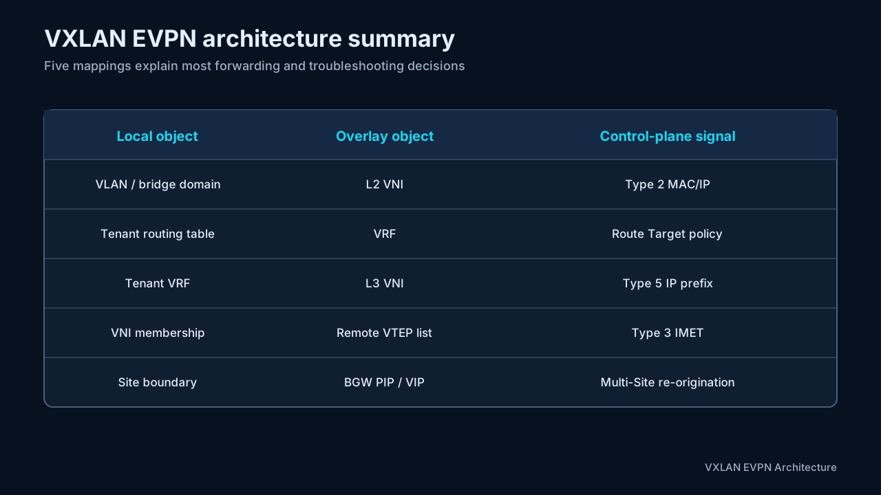
That separation of responsibilities is the central idea of VXLAN EVPN architecture: a simple routed fabric underneath, policy-rich tenant overlays above it, and explicit control points wherever scale or failure isolation requires another boundary.
Appendix A: EVPN Type 1 and Type 4 multihoming reference
Many common VXLAN EVPN fabrics primarily use Type 2 routes for endpoint reachability, Type 3 routes for BUM membership, and Type 5 routes for IP prefixes. Type 1 and Type 4 routes appear when the fabric uses standards-based EVPN Ethernet-segment multihoming with a nonzero ESI. A design based on vPC, MLAG, or another vendor-specific dual-homing mechanism may provide link redundancy without advertising Type 1 or Type 4 routes. Their absence is therefore not automatically a fault; first identify the attachment model.
This appendix keeps the Type 1 and Type 4 behavior available as a general EVPN reference without implying that every VXLAN EVPN fabric uses it.
A.1 Worked scenario: why Type 4 and Type 1 are both needed
Assume Server-01 forms one all-active LACP bond to Leaf-A and Leaf-B. Both leaves use the same nonzero ESI-10 for the bond and place VLAN 110 in the same EVI (encoded as L2 VNI 10110 on this VXLAN fabric). Leaf-C is a remote PE in that EVI. For this example, Leaf-A is the Designated Forwarder (DF) for VLAN 110.
(Type 1 and Type 4 are RFC 7432 EVPN mechanisms, independent of the data-plane encapsulation. This reference therefore uses the standards term PE for the routing device rather than the VXLAN-specific VTEP; on a VXLAN fabric each PE is simply a leaf VTEP.)
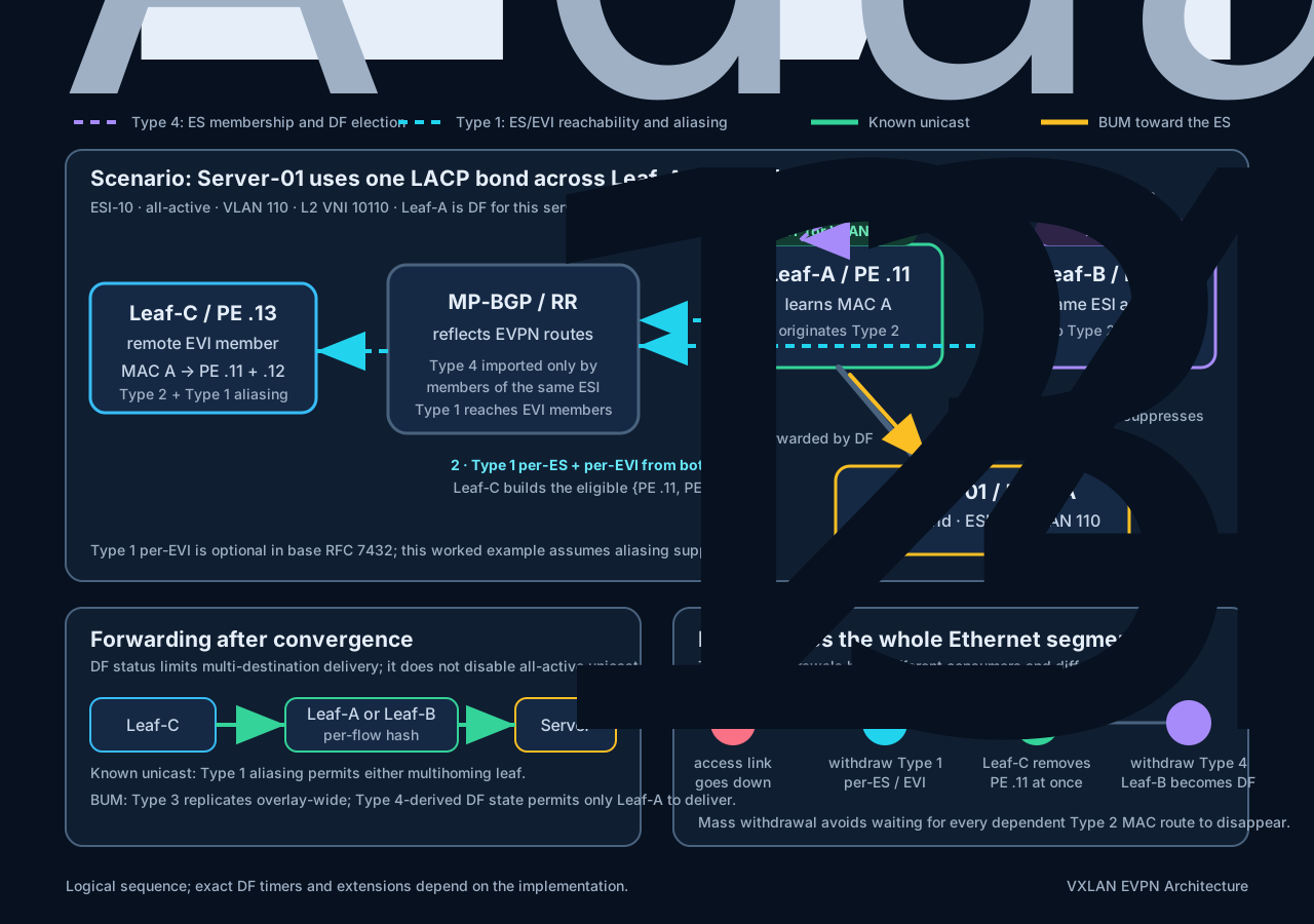
The numbered control-plane steps establish two different kinds of state. Type 4 coordinates the leaves attached to the Ethernet segment; Type 1 tells remote PEs how that segment and service can be reached.
A.2 Control-plane flow
- The multihoming leaves advertise Type 4 ES routes.
Leaf-AandLeaf-Badvertise the same ESI with their own originator IP addresses. The ES-Import Route Target limits import to leaves attached to that Ethernet segment, so the two leaves discover each other while remoteLeaf-Cnormally does not import the Type 4 routes. The resulting candidate set is used for DF election. RFC 7432, Sections 8.1 and 8.5 - Each leaf advertises Type 1 A-D routes. A per-ES route represents reachability to the entire Ethernet segment and enables mass withdrawal. A per-EVI route represents the leaf’s participation in that EVI on the segment and enables aliasing for that service. Type 1 per-EVI advertisement is optional in the base specification; this scenario assumes the implementation supports and advertises it. RFC 7432, Sections 8.2 and 8.4
- Only one leaf needs to originate the host’s Type 2 route. Suppose LACP hashes the first source frame from
Server-01toLeaf-A.Leaf-Alearns MAC A and advertises a Type 2 MAC/IP route containingESI-10.Leaf-Bmay not yet have learned that MAC. - The remote PE creates an aliased next-hop set.
Leaf-Ccorrelates the Type 2 route fromLeaf-Awith the Type 1 per-EVI advertisements for the same ESI and EVI. It can therefore install bothPE .11andPE .12as eligible next hops for MAC A instead of pinning traffic to the Type 2 originator.
Aside — EVI versus ESI. An EVI (EVPN Instance) is one logical Layer-2 forwarding domain inside an EVPN network — roughly a VLAN or bridge domain extended across the fabric. A customer VLAN maps to an EVI, and every PE participating in that EVI exchanges reachability for the same broadcast domain; in VXLAN EVPN the EVI is commonly associated with an L2 VNI. In this scenario, VLAN 110 → EVI → VNI 10110.
The two identifiers answer different questions — ESI identifies the physical or logical multihomed segment (ESI-10 here), while EVI identifies the EVPN service carried over it. That is exactly why the two route types read the way they do in plain terms:
- Type 4 says: “this PE is attached to Ethernet segment
ESI-10.” - Type 1 per-EVI says: “this PE can reach
ESI-10specifically within EVI / VLAN 110 (VNI 10110).” - Type 1 per-ES represents the Ethernet segment across all its EVIs, and enables bulk / mass withdrawal.
A.3 Forwarding flow after convergence
- Known unicast:
Leaf-Ccan hash different flows to eitherLeaf-AorLeaf-B. All-active unicast is still active through both leaves; DF status does not reduce it to a single path. - BUM traffic toward the server: Type 3 Inclusive Multicast routes supply the overlay BUM replication membership. If both multihoming leaves receive a copy, only the Type 4-derived DF,
Leaf-A, forwards it toward the Ethernet segment; non-DFLeaf-Bsuppresses its copy. Type 4 therefore selects the delivery leaf, but it does not build the overlay replication list.
A.4 Failure flow when Leaf-A loses the whole Ethernet segment
Leaf-Awithdraws its Type 1 per-ES route and the affected per-EVI route.Leaf-CremovesPE .11from all affectedESI-10aliasing sets at once. It does not need to wait for every dependent Type 2 MAC route to age out or be withdrawn individually.Leaf-Awithdraws its Type 4 ES route because it is no longer attached to the segment.Leaf-Bis now the remaining DF candidate and becomes DF; known unicast and BUM delivery continue through it.
If only VLAN 110 fails while the physical Ethernet segment remains up, the per-EVI Type 1 withdrawal gives the narrower, service-specific signal. Implementations that support the RFC 8584 AC-DF capability can also use Type 1 service availability to remove an ineligible leaf from that service’s DF candidate list. RFC 8584, Section 4
A.5 Route responsibility summary
| Question | Route or state that answers it |
|---|---|
| Which leaves belong to this Ethernet segment, and which is DF? | Type 4 ES route |
| How can remote PEs rapidly invalidate reachability to the whole segment? | Type 1 per-ES A-D route |
| Which leaves can reach this ESI in that EVI for aliasing? | Type 1 per-EVI A-D route |
| Where was MAC A learned? | Type 2 MAC/IP route carrying the ESI |
| Which PEs receive overlay BUM copies? | Type 3 Inclusive Multicast route |
A.6 Alternative three-step CE/PE example
Where A.1–A.5 stayed at the standards abstraction — PEs, Ethernet segments, and the EVI — this second telling deliberately drops down to the VXLAN encoding of that same EVI, the L2 VNI, so you can see how the two connect. (A.6.2 makes the mapping explicit via RFC 8365.)
The example uses vendor-neutral CE/PE terminology. A customer-edge switch is dual-homed in all-active mode to PE1 and PE2 through one LACP bundle. Both PEs identify the attachment as ESI 01; local VLAN 110 maps to L2 VNI 10110. Remote PE3 participates in the same EVPN service but is not attached to ESI 01.
Keep these route responsibilities separate:
- Type 4 - Ethernet Segment route: lets
PE1andPE2discover that they share the Ethernet segment and establish the DF candidate set. The resulting DF state prevents duplicate BUM delivery toward the CE. - Type 1 - Ethernet A-D route: advertises per-ES and per-EVI reachability. It supports service aliasing/load sharing and rapid mass withdrawal after an attachment failure.
- Type 2 - MAC/IP route: advertises the individual endpoint MAC. Type 1 does not carry the endpoint MAC address.
A.6.1 Discover the Ethernet segment with Type 4
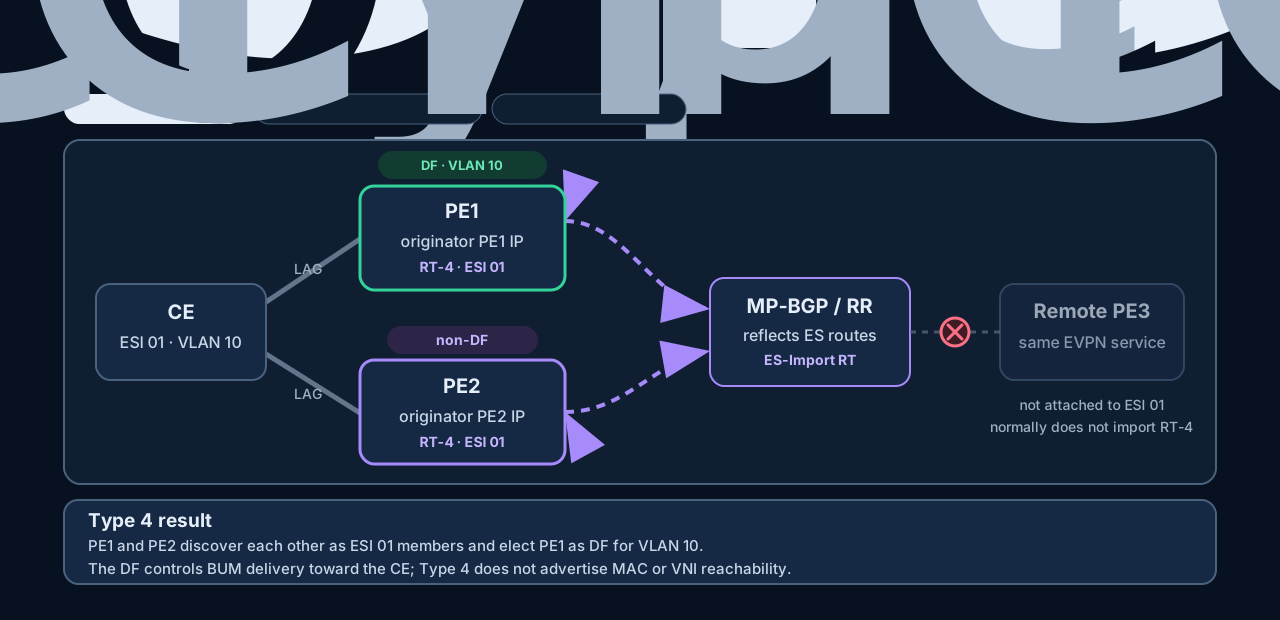
PE1 and PE2 each advertise a Type 4 route containing ESI 01, their originating PE address, and an ES-Import Route Target. A route reflector may carry the BGP updates, but only PEs attached to that Ethernet segment import and use them. Remote PE3 is in the EVPN service but not in ESI 01, so it normally does not import these Type 4 routes.
The same-ES PEs then perform DF election for the service. If PE1 is DF for VLAN 110, it delivers received BUM traffic toward the CE while PE2 suppresses the duplicate. Type 3, not Type 4, constructs the overlay BUM replication membership. Known unicast can still use either PE in all-active mode. RFC 7432, Sections 8.1 and 8.5
A.6.2 Advertise reachability with Type 1
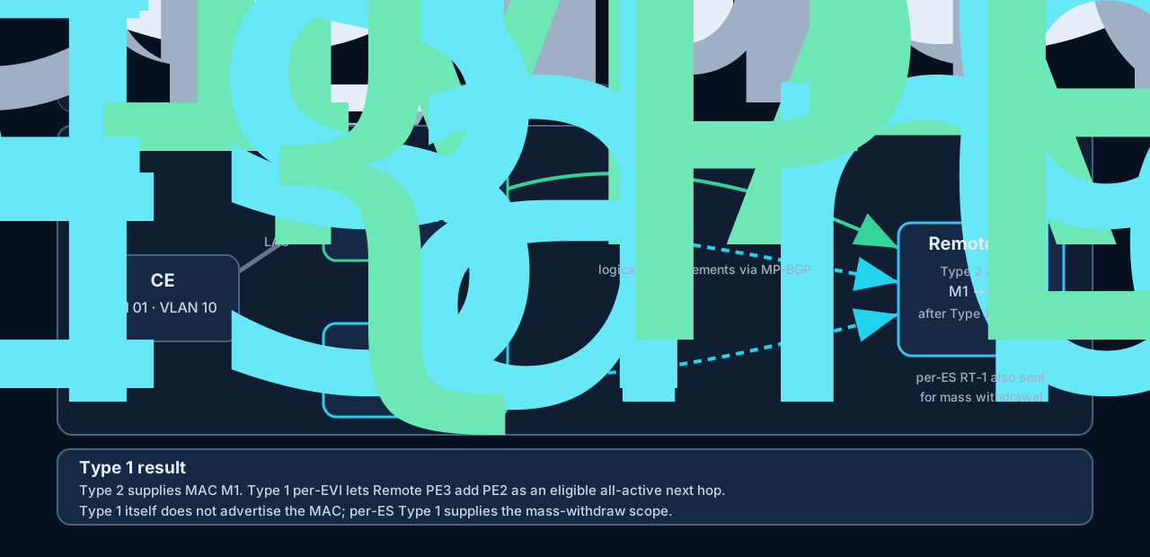
Both multihoming PEs advertise Type 1 per-ES routes for whole-segment reachability and mass withdrawal. They also advertise Type 1 per-EVI routes for ESI 01 and L2 VNI 10110 so a remote PE can identify every eligible next hop for that service.
Suppose only PE1 learns endpoint MAC M1 and advertises its Type 2 route with ESI 01. Remote PE3 combines that Type 2 route with the Type 1 per-EVI routes from both PEs and expands the next-hop set from {PE1} to {PE1, PE2}. This is aliasing: Type 2 identifies the MAC, while Type 1 identifies the additional path through the same Ethernet segment. RFC 7432, Section 8.4
In a VXLAN service, describe this control-plane association using the EVI/L2 VNI, not only the locally significant VLAN number. RFC 8365 maps the VNI into the EVPN route’s label field. RFC 8365, Section 5.1.3
A.6.3 Withdraw the failed attachment
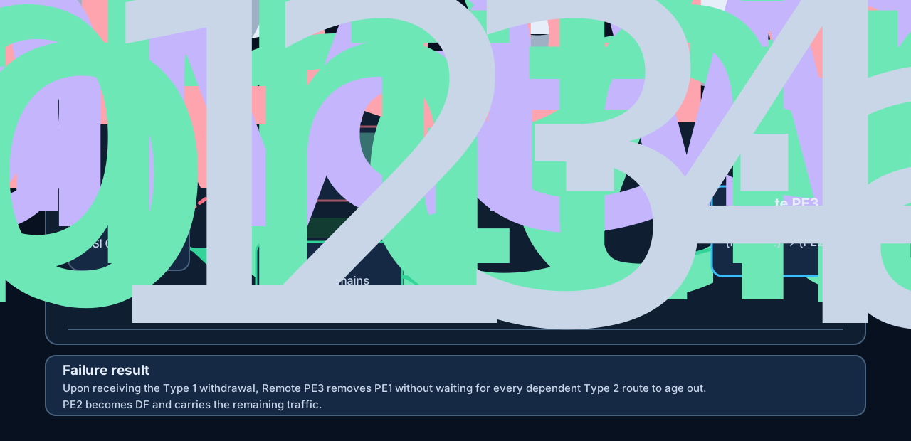
When the entire CE-to-PE1 attachment fails:
PE1withdraws its Type 1 per-ES route and the affected per-EVI route.- Upon receiving the withdrawal,
Remote PE3removesPE1from the next-hop sets associated withESI 01and VNI 10110. Traffic continues throughPE2without waiting for every dependent Type 2 route to age out. PE1also withdraws its Type 4 route because it is no longer attached to the Ethernet segment.PE2becomes the remaining DF candidate and takes over BUM delivery toward the CE. RFC 7432, Sections 8.2 and 17.3
If only the VLAN 110 service fails while PE1 remains attached to the Ethernet segment for other services, the failure is narrower: withdraw the affected per-EVI reachability rather than the whole per-ES and Type 4 state. An implementation supporting AC-aware DF election can also remove PE1 from that service’s DF candidate list. RFC 8584, Section 4